

3299W-1-103LF: Package, Specs, and How Buyers Verify Lots
3299W-1-103LF pinout, package, and datasheet limits buyers actually check — plus lot inspection notes. Request a quote on IC-Online; no invented stock claims.
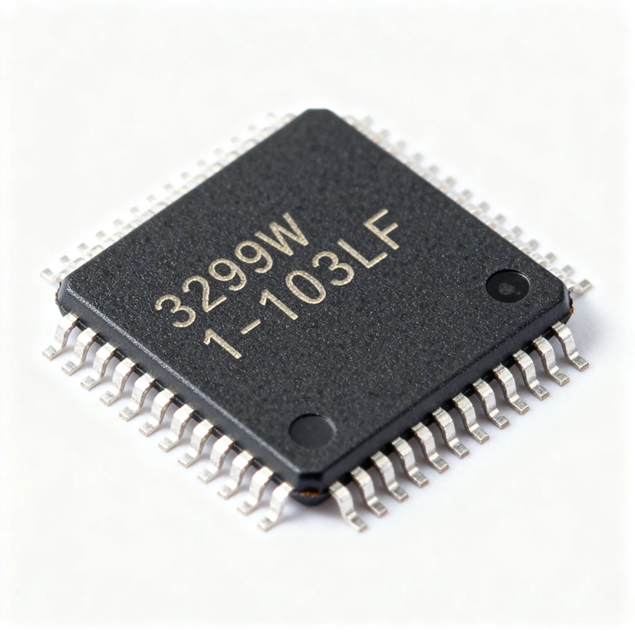
3299W-1-103LF: Package, Specs, and How Buyers Verify Lots
Why a $0.50 Trimmer Can Trip Up a Production Run
A 25‑turn cermet trimmer potentiometer like the 3299W-1-103LF rarely makes headlines. It costs less than a dollar, occupies a few square millimeters of PCB real estate, and quietly biases an ADC reference or sets a comparator threshold. Yet when incoming inspection catches a lot with contaminated wipers, inconsistent contact resistance, or — worse — a reel of parts that turns out to be remarked commercial rejects, the consequences cascade. A single faulty trimmer in a voltage reference chain can shift gain across an entire sensor front-end, forcing a line stoppage, rework, and field returns.
Ongoing coverage by EE Times has underlined how even passive components are not immune to counterfeit infiltration, especially as supply chains stretch and gray-market brokers become more aggressive. For procurement teams managing high-mix, low‑volume production, the burden falls on verifying every lot of commodity passives before they reach an SMT line. The 3299W-1-103LF from Bourns serves as an excellent case study: its side‑adjust siblings, date‑code marking conventions, and part‑number logic are well‑documented, making it possible to build a rigorous verification workflow that catches anomalies early.
This article unpacks the package design, electrical profile, and multi‑source comparison points for the 3299W-1-103LF, then walks through a step‑by‑step incoming‑inspection sequence that buyers and quality engineers can adopt today. No stock claims or lead‑time forecasts are made — instead, every recommendation is anchored in publicly available datasheets, manufacturer markings, and industry‑standard traceability principles defined by IPC.
Decoding the 3299W-1-103LF: Package Layout, Pinout and Electrical Profile
Bourns encodes mechanical configuration and electrical value directly into the part number. For the 3299W-1-103LF, the breakdown is:
- 3299 – series indicator for a 3/8″ square, multi‑turn cermet trimmer.
- W – top‑adjust orientation; the adjustment screw sits on the upper face, allowing in‑circuit access from above the board.
- 1 – pin style code. “1” denotes three in‑line PCB pins with a standard 0.100″ (2.54 mm) pitch.
- 103 – resistance code: “10” followed by three zeros, equating to 10 kΩ.
- LF – lead‑free terminal finish (pure‑tin plating), meeting RoHS and REACH requirements.
The physical package is a 9.53 mm (0.375″) square housing, with an overall seated height of approximately 6.35 mm (0.250″) for the top‑adjust W style. The three pins — wiper, one end terminal, and the other end terminal — are arranged in a single row along the bottom edge. Pin identification follows the standard pattern: when viewing the trimmer from the top with the adjustment screw centered and the pins projecting downward, the center pin is the wiper, the left pin is terminal 1 (CW end), and the right pin is terminal 2 (CCW end). This assignment must be confirmed with the Bourns 3299 series datasheet during PCB footprint creation to avoid mirrored connections.
Assembly quality guidelines from IPC‑A‑610 classify through‑hole components like the 3299W-1-103LF as acceptable when the termination is visible in the solder fillet, the lead protrusion meets minimum requirements, and there is no evidence of cracked bodies from excessive mechanical stress. In wave‑soldered processes, the plastic housing should be held slightly above the board surface to survive preheat and solder wave thermal shock — a detail that often gets overlooked when CAD footprints are copied from old libraries.
Key Electrical and Mechanical Specifications
| Parameter | Value/Range | Unit/Notes |
|---|---|---|
| Resistance (nominal) | 10 | kΩ |
| Resistance tolerance | ±10 | % |
| Power rating (70 °C) | 0.5 | W |
| Temperature coefficient (TCR) | ±100 | ppm/°C (cermet element) |
| Adjustment turns (nominal) | 25 | Turns (electrical) |
| Contact resistance variation (CRV) | ≤1% or 3 Ω, whichever is greater | As measured per Bourns spec |
| End resistance | ≤2 | Ω |
| Operating temperature range | −55 to +150 | °C |
| Mechanical dimensions (square footprint) | 9.53 × 9.53 | mm (0.375 × 0.375 in) |
| Height (top‑adjust, seated) | 6.35 | mm (0.250 in) |
| Pin pitch | 2.54 | mm (0.100 in) |
| Terminal finish | Pure tin (LF suffix) | RoHS compliant, reflow/wave solderable |
All numbers above come directly from the Bourns 3299 series datasheet; they should be cross‑checked against the official document available on Bourns.com. The combination of 25‑turn resolution and a ±100 ppm TCR makes the 3299W-1-103LF suitable for precision biasing applications where a single‑turn pot would not deliver enough granularity.
How the 3299W-1-103LF Stacks Up Against Other Multi-Turn Trimmers
Bourns offers multiple mechanical variants within the same 3299 family, and competing manufacturers supply parts with similar footprints. A direct substitution that overlooks adjustment orientation or pin‑row offset will almost certainly break the mechanical fit, forcing a PCB respin. The side‑adjust 3299X, for instance, retains the same 10 kΩ value and 25‑turn count but routes the screw from the side face, requiring a board cutout for access. The 3299Y and 3299Z extend the pin row to a 0.200″ pitch or adopt a different pin‑out, so footprint reuse is impossible without a new layout.
From an electrical standpoint, alternative trimmers from Vishay/Spectrol (Model 43 series) or TT Electronics (e.g., 3296‑compatible parts) often match the resistance tolerance and power rating, but their TCR, wiper current handling, and mechanical rotational life may differ. For high‑reliability designs that expect thousands of adjustment cycles over the product lifetime, the cermet element formulation from each supplier can yield different CRV drift profiles. Any change must be evaluated with physical samples and a full qualification run.
Comparison Matrix: Key Mechanical and Electrical Differences
| Metric | Bourns 3299W-1-103LF | Bourns 3299X-1-103LF (side‑adjust) | Vishay/Spectrol Model 43 (10 kΩ, top‑adjust) | Selection Criteria & Failure Boundary |
|---|---|---|---|---|
| Adjustment orientation | Top‑adjust (vertical access) | Side‑adjust (horizontal access) | Top‑adjust, similar vertical footprint | Board cutout and enclosure clearance must be verified. A 3299X cannot replace a W without a mechanical redesign. |
| Mounting height | 6.35 mm | ~5.84 mm base height,± depending on orientation | 6.10 mm seated | Height difference can interfere with heatsinks or daughter cards. Measure from top of PCB to top of adjustment screw. |
| Pin pitch | 2.54 mm in‑line | 2.54 mm in‑line | 2.54 mm in‑line | Footprint identical only if pin‑1 location matches; confirm datasheet pinout against legacy library. |
| Resistance tolerance | ±10% | ±10% | ±10% (standard) | Tight‑tolerance options may be available; request allocation‑backed samples for verification. |
| TCR (cermet) | ±100 ppm/°C | ±100 ppm/°C | ±100 ppm/°C | In precision analog circuits, a 50 ppm difference can shift bias points across a wide temperature swing. Check your error budget. |
| Adjustment turns | 25 | 25 | 25 | Identical turn count, but wiper contact resistance variation may differ; always sample CRV on first‑article lots. |
Tip: When evaluating a cross‑reference, request the full mechanical drawing and a 3D STEP model from the alternate supplier. Even 0.2 mm height differences can create assembly interference in dense enclosures. Never assume drop‑in interchangeability — verify pinout, TCR, and wiper noise with bench measurements on at least five samples from three different date codes.
From Date Code to Lot Traces: How Buyers Can Verify 3299W-1-103LF Lots
An effective incoming inspection plan for the 3299W-1-103LF combines visual checks, electrical measurements, and documentation traceability. The goal is to identify any mismatch with the manufacturer’s certified lot before parts enter stock, reducing the risk of field failures. The following workflow aligns with IPC traceability principles and can be executed with a DMM, a fixture, and a loupe — no high‑end ATE required.
Verification Steps
- Date code decode and marking consistency. Bourns typically uses a four‑digit YYWW format laser‑etched on the component body or printed on the reel label. For example, “2315” translates to week 15 of 2023. Inspect every device under 10× magnification; if any unit shows an entirely different font, incomplete marking, or a code inconsistent with the reel label, isolate the lot.
- Lot identification and distributor certification. The reel label carries the Bourns lot ID alongside the part number and quantity. Cross‑reference the lot ID against the distributor’s certificate of conformance (C of C) and the packing slip. A missing or altered lot ID on either the reel or the certificate is a red flag for gray‑market diversion. Request the IPC‑1782 traceability matrix from your supplier if you require full provenance.
- Total resistance and end resistance check. Using a calibrated 4‑wire DMM, measure the end‑to‑end resistance. For a nominal 10 kΩ ±10% part, all units should fall between 9 kΩ and 11 kΩ at room temperature. Then measure resistance from the wiper to each end terminal with the wiper set fully clockwise and counter‑clockwise. The end resistance should read ≤2 Ω. High end resistance suggests a contaminated wiper contact or oxidation on the terminal.
- Wiper contact resistance variation (CRV) sampling. Connect a DMM between the wiper and one end terminal. Rotate the adjustment screw slowly through the full 25‑turn range while monitoring resistance fluctuation. A healthy cermet trimmer will show smooth, predictable change. Sudden jumps or noise spikes exceeding 1% of total resistance (or 3 Ω, whichever is greater) indicate CRV beyond the Bourns spec and can compromise circuit linearity.
- Packaging verification and reel match. Confirm that the tape‑and‑reel orientation matches the manufacturer’s standard (usually per EIA‑481). Check that the component quantity on the reel label equals the physical count (a weight‑based verification is acceptable). Discrepancies between the label and the count often accompany remarking operations.
Quick‑Reference Incoming Inspection Table
| Check | Acceptance Criteria | Tool/Action |
|---|---|---|
| Date code / marking | Consistent laser‑etched YYWW, matches reel label | 10× loupe, reel label photo archive |
| Lot ID traceability | Lot ID on reel = C of C lot ID; distributor certificate present | Supplier portal, document comparison |
| Total resistance | 9 kΩ to 11 kΩ at 25 °C | 4‑wire DMM, test fixture |
| End resistance | ≤2 Ω at both end stops | DMM, screwdriver |
| CRV (wiper noise) | ≤1% of total resistance (or 3 Ω, whichever is greater), no sudden jumps | DMM with data‑logging or oscilloscope |
| Packaging label vs. physical count | Quantity on label equals counted (by weight or unit) | Counting scale, visual reel check |
All the above checks assume that the parts arrived in factory‑sealed packaging from a known authorized channel. If the packaging appears tampered‑with or the lot ID has been re‑applied with a sticker over the original label, quarantine the shipment immediately and alert your quality team. Buyers should also request a test report within 90 days from the distributor for high‑reliability programs — this is a Tier‑B requirement, not a statement about current supply.
When the 3299W-1-103LF passes all tests, record the results with the lot number in your ERP system. This creates an auditable trail that directly supports IPC‑175x material declaration workflows and simplifies any future root‑cause investigation.
Buyer and Engineer Questions on the 3299W-1-103LF
Procurement professionals and design engineers regularly encounter ambiguity around date‑code reading, RoHS compliance suffixes, and interchangeability. Below we address the most frequent questions, grounded in Bourns documentation and practical field experience.
Q: How do I decode the date code on a Bourns 3299W trimmer?
Bourns typically uses a four‑digit YYWW format on both the component body and the reel label. The first two digits represent the two‑digit year (e.g., “23” for 2023), and the last two represent the calendar week (01–52). Thus, “2315” would denote week 15 of 2023. The marking is applied via laser and should be clear under magnification. If a lot shows a mixture of ink‑stamped and laser‑etched codes, escalate for authentication, as the 3299W series has been laser‑marked for many years.
Q: What does “103LF” stand for, and why is LF crucial for RoHS compliance?
“103” is the resistance value code: “10” followed by three zeros, meaning 10 kΩ. “LF” means lead‑free, indicating that the terminal plating is pure tin (matte tin) rather than tin‑lead. The 3299W-1-103LF is fully RoHS‑compliant, and the LF suffix is the factory’s way of certifying that the terminations do not contain lead. If your BOM accidentally omits the LF suffix, procurement could inadvertently source the non‑compliant version (3299W‑1‑103) that may still exist in some inventories. For EU, China RoHS, and REACH‑regulated markets, LF must be present on the purchase order and verified during incoming inspection.
Q: Can I substitute a 3299W-1-103LF with a 3299X-1-103LF on the same PCB?
No. The 3299W-1-103LF is a top‑adjust trimmer with the screw accessible from the upper face, while the 3299X-1-103LF is a side‑adjust part requiring a horizontal access path. The two packages share the same pin pitch but differ in the physical location of the adjustment screw relative to the board. Swapping them will likely cause the screw to face an adjacent component or an enclosure wall, making in‑circuit calibration impossible. Additionally, the board cutout for a side‑adjust part is not present on a top‑adjust layout, so a mechanical collision may occur. The electrical ratings are similar, but the form‑fit mismatch precludes a drop‑in. Consult the Bourns 3299 series datasheet for the exact dimensions of each style.
Q: Does lot‑to‑lot variation affect wiper noise or long‑term stability?
Bourns cermet trimmers exhibit good lot‑to‑lot consistency, but process shifts can introduce marginal changes in contact resistance variation (CRV) or temperature coefficient. In our experience, the CRV may drift from a typical <1% to the maximum rated 2% in outlier lots, especially if the wiper alloy composition or cermet firing profile shifted. Incoming inspection should sample CRV on a statistically significant number of units per lot (20–30 pieces) to detect such shifts. Long‑term stability is primarily a function of the cermet element’s inherent drift, which Bourns specifies at ±1% maximum after 1000 hours at rated power and 70 °C. Verify the lot’s compliance by asking for a batch test report if the application is sensitive to drift.
Q: What quick tests at incoming inspection help weed out counterfeit 3299W-1-103LF trimmers?
Counterfeit trimmers often fail simple consistency checks. A 10× loupe inspection of the marking: genuine Bourns parts have crisp, uniform laser etching; fake devices may show fuzzy, shallow marks or a painted code that smears. Resistance measurement: total resistance out of tolerance (e.g., 7 kΩ or 15 kΩ) or end resistance >5 Ω is a strong indicator. Rotating the screw to the end stop and feeling for a positive, clean stop (no gritty texture) can expose mechanically inferior copies. Finally, verify the reel label’s lot ID against the distributor’s traceability system — if the distributor cannot produce a certificate of conformance with the same lot number, the parts should be treated as suspect. Any mismatch warrants quarantining the lot and performing a full authenticity analysis, possibly including X‑ray inspection to compare internal structures.
By integrating these checks into standard receiving protocols, procurement and quality teams can protect production from the type of passive‑component failures that EE Times has highlighted as an ongoing weak point in the electronics supply chain.
References & Further Reading
- Bourns 3299 Series Datasheet — Official Package, Pinout and Electrical Specifications
- EE Times — Electronics Engineering News and Supply Chain Coverage
- IPC Standards — IPC‑A‑610, IPC‑1782, IPC‑175x for Assembly Quality and Traceability
- Bourns Trimpot® Product Line Overview
- 3299W-1-103LF on IC-Online — Request Quote and Verify Current Allocation
- Trimmer Potentiometers Category on IC-Online — Compare Multi‑Turn Options
Conclusion: The 3299W-1-103LF is a workhorse component whose reliable performance depends on receiving authentic, in‑spec production lots. By decoding the part‑number logic, comparing package styles precisely, and executing a disciplined incoming‑inspection sequence, buyers and engineers can avoid the costly trap of mis‑sourced trimmers. Whether you are qualifying an alternate source or verifying a new shipment, the combination of date‑code audits, resistance and CRV measurements, and lot‑level traceability provides a solid defense against gray‑market risks. When supply tightens or your BOM expands to include trimmers, connectors, and ICs from multiple families, confirm allocation‑backed availability and lead time by requesting a quote. Use IC-Online’s RFQ platform to upload your full BOM and receive competitive pricing with flexible MOQs — no stock or lead‑time numbers are asserted here; every order is confirmed against live supplier inventories.