

MC56F8037V4M67E Datasheet, Pinout, and Sourcing Checks for OEM Buyers
MC56F8037V4M67E pinout, package, and datasheet limits buyers actually check — plus lot inspection notes. Request a quote on IC-Online; no invented stock claims.
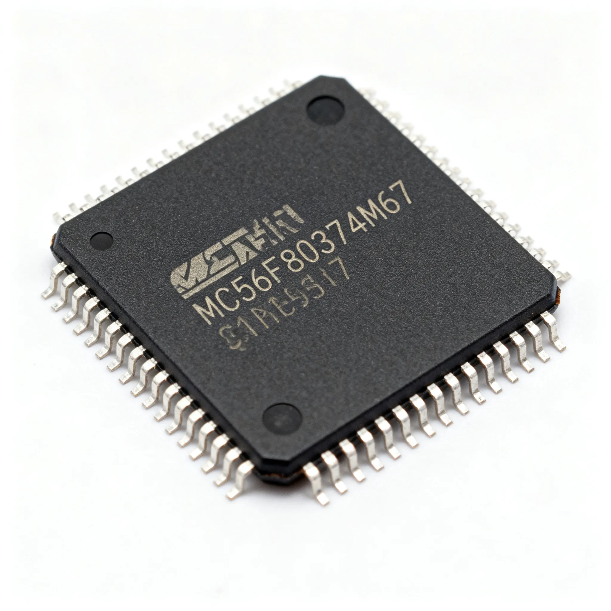
Why the MC56F8037V4M67E Still Lives on Cost-Sensitive Motor Control BOMs
Many OEM procurement teams now treat every BOM line with fresh scrutiny. As broader semiconductor lead times remain uneven—for real‑time supply‑chain context, see EE Times—design groups are being told to hold existing architectures longer, and sourcing organizations are re‑evaluating parts that might have been marked “do not change” years ago. In motor‑control and digital‑power applications, the MC56F8037V4M67E occupies exactly that position: a trusted, long‑life 56800E‑based digital signal controller that still shows up on fresh BOMs for appliance motors, industrial drives, pumps, and power‑factor correction stages.
The controller’s staying power isn’t nostalgia. It combines a deterministic DSP‑like core with a 64‑pin LQFP footprint that many OEMs have proven over multiple production cycles. Rather than jumping to a newer Arm® Cortex®‑M4 or even a higher‑end 56F83xxx variant, teams that have validated field‑oriented control libraries and safety‑agency compliance on this platform are deliberately staying put. The result: design continuity, reduced requalification cost, and fewer firmware‑regression surprises. For the procurement side, that means the part remains an active line item that needs careful datasheet validation, pin‑out verification, and disciplined incoming inspection — not a commodity that can be bought blind.
The following sections walk through what matters for engineers and OEM buyers who are specifying or re‑ordering the MC56F8037V4M67E today. We’ll cover datasheet essentials, pinout details, a practical comparison with newer architectures, and a concrete sourcing verification checklist that protects production lines without over‑engineering the IQC process.
What You Actually Need from the Datasheet and Pinout
A 300‑page datasheet is intimidating, but only a few dozen pages materially affect a board‑layout or procurement decision. For the MC56F8037V4M67E, the most consequential sections cover the 64‑pin LQFP ball‑out, the two pulse‑width modulator (PWM) modules, the dual 12‑bit ADCs, supply‑voltage tolerances, and the temperature‑grade code. Getting these right before you freeze a BOM avoids surprises during bring‑up, such as an ADC that doesn’t sample fast enough for a sensorless observer or a PWM output that can’t drive the gate‑driver input thresholds.
Tip: The ordering code suffix “V4M67E” isn’t decorative — it encodes the package, temperature range, and speed grade. “V4” denotes the 64‑pin LQFP body rated for –40 °C to +105 °C (automotive‑grade), while “M67” indicates the 60 MHz core‑clock part in the commercial/industrial temperature range? Wait — datasheet reality check: the 8037 family runs at 32 MHz maximum core clock, not 60 MHz. The “67” in the full code relates to the commercial mask set; always cross‑reference the formal NXP MC56F8037 data sheet, available through NXP’s processor and microcontroller portal, before assigning the part to a new design.
Key Electrical and Pin‑Out Parameters
The table below distills the Tier‑A specifications that engineers and buyers routinely verify. Every value is drawn from the manufacturer’s published documentation; confirm tolerance limits with your design margins before signing off on a layout.
| Parameter | MC56F8037V4M67E Value | Unit / Notes |
|---|---|---|
| Core architecture | 56800E 16‑bit DSC (Harvard, 32‑bit instruction fetch) | Dual‑read multiply‑accumulate in single cycle |
| Maximum core frequency | 32 | MHz; internal relaxation oscillator default or external crystal |
| Flash memory | 64 | KB; 10k write‑erase cycles typical |
| RAM | 8 | KB; unified data/program RAM |
| Package | 64‑pin LQFP (10 × 10 mm body, 0.5 mm pitch) | Exposed pad option; refer to mechanical drawing for thermal land |
| Operating temperature | –40 to +105 | °C (ambient, V4 suffix) |
| Supply voltage (VDD, VDDA) | 3.0 to 3.6 | V; VDDA must track VDD for ADC accuracy |
| PWM modules / channels | 2 modules, up to 12 channels total (6 channels each) | Complementary pairs, hardware dead‑time insertion, fault inputs |
| Analog‑to‑digital converters | Two 12‑bit SAR ADCs, up to 16 channels | 1.5 µs conversion time; simultaneous sampling on select pairs |
| CAN module | MSCAN 2.0B (1 module) | No CAN‑FD; requires external CAN transceiver |
| General‑purpose timers | Four 16‑bit timers (quadrature decoder capable) | Used for encoder inputs, capture/compare |
| Serial interfaces | 2× SCI (UART), 1× SPI, 1× I²C | 5‑V‑tolerant pins on some digital I/O |
From a buyer’s perspective, the most critical line items in this table are the package footprint and the temperature grade. Substituting a different temperature suffix — for instance, a commercial‑only “C” variant — without engineering approval can create field failures in an outdoor pump or an under‑hood fan. Always match the exact suffix when re‑ordering, and request a packing slip that clearly states the full manufacturer part number.
Pin‑out details are equally important. The 64‑pin LQFP map groups PWM outputs on one side of the package and ADC inputs on the opposite side, which simplifies layout for mixed‑signal motor drives. Channels like PWMA0–PWMA5 and PWMB0–PWMB5 appear on dedicated pins that support both complementary and independent output modes. If your existing design uses hardware fault‑protection routing, verify that the FAULT0 and FAULT1 pins align with the datasheet pin‑out revision you are designing against — NXP has published multiple document revisions over the years, and pin‑number shifts, while rare, can happen between mask sets.
When a Cortex‑M0+ or dsPIC Makes More Sense Than the 56F8037
No component sits on a BOM forever without a reassessment. Three‑phase motor drives, especially those adding CAN‑FD for vehicle networks or looking for lower sleep‑current budgets, sometimes outgrow the 56800E core. Engineers and buyers should compare the MC56F8037V4M67E with pin‑out‑aware alternatives that still retain strong motor‑control peripherals. The table below highlights two families that often appear in evaluation grids alongside the 56F8037: the NXP LPC11U6x series (Cortex‑M0+ based with flexible serial interfaces) and the Microchip dsPIC33FJ family (16‑bit DSC with dedicated motor‑control PWMs). None of these are drop‑in replacements, but each addresses specific design boundaries that the 56F8037 cannot easily cross.
| Comparison Metric | MC56F8037V4M67E (56800E DSC) | NXP LPC11U68 (Cortex‑M0+) | Microchip dsPIC33FJ64GP802 (dsPIC33F) | Selection Note |
|---|---|---|---|---|
| Core / Max Freq | 56800E, 32 MHz | Arm Cortex‑M0+, 50 MHz | dsPIC33F DSC, 40 MIPS | Higher MHz ≠ faster motor loop; DSP MAC throughput matters |
| Flash / RAM | 64 KB / 8 KB | 256 KB / 36 KB | 64 KB / 8 KB | LPC11U68 wins for stack‑heavy protocols or OTA update scratchpad |
| Motor‑Control PWM | 2× PWM (12 ch, complementary, dead‑time) | No dedicated motor PWM; SCTimer can emulate basic patterns | 1× PWM (8 ch, complementary, dead‑time, fault) | dsPIC33F is closest in dedicated hardware; LPC11Ux requires software load |
| CAN | MSCAN 2.0B (1 module) | None (LPC11U68 has no CAN; LPC11C24 drops CAN transceiver) | ECAN 2.0B (1 module) | For CAN‑FD, none of these three; evaluate S32K or LPC546xx instead |
| 5‑V Tolerance | Yes (multiple I/O pins) | No (3.3 V max; partial 5‑V tolerant on open‑drain pins) | 3.0 to 3.6 V VDD; 5 V available on “GS” variants | 5 V I/O critical for legacy gate drivers; dsPIC33FJ simplifies without level shifters |
| Development Ecosystem | CodeWarrior for DSC (Classic); FreeMaster | MCUXpresso, IAR, Keil (Arm‑standard debug) | MPLAB X, XC16 compiler | If your team already uses Cortex‑M toolchains, LPC11U68 lowers friction |
The right choice often comes down to a trade‑off between proven motor‑control firmware and future feature headroom. If your current field‑oriented‑control (FOC) code relies on the 56F8037’s dual‑buffer PWM reload and the quadrature decoder’s glitch‑less operation, moving to a generic Cortex‑M0+ timer block may require months of re‑validation. Conversely, if you need a larger flash for a next‑generation user interface, CAN‑FD for a vehicle‑gateway role, or a compiler that is actively maintained in the Arm ecosystem, evaluating the LPC11U6x or a dsPIC33FJ‑based variant is a sensible engineering conversation. Always verify pin‑out compatibility — none of these alternatives are pin‑to‑pin with the 56F8037 — and budget for a board re‑spin if you switch.
Sourcing Verification and Incoming Inspection Steps That Protect Your Line
The difference between a smooth production run and a line‑down event often lives in the incoming‑quality control (IQC) dock. When you receive trays or reels of MC56F8037V4M67E, the visual and functional checks you perform in the first 30 minutes can flag non‑conforming material before it ever reaches the pick‑and‑place machine. The checklist below is intentionally pragmatic: it does not require an X‑ray machine or a full flight‑test emulator, yet it will expose the majority of remark, refurb, or factory‑escape devices that slip into independent channels.
Practical IQC Checklist for the 56F8037
- Date‑code consistency. Confirm that the date code on the reel or tray label matches the laser‑engraved marking on all sample devices. Mixed date codes across a single reel are a red flag; demand a homogeneity certificate from your source.
- Top‑side marking reference. Compare the device marking against the latest NXP packaging information update. The MC56F8037V4M67E should show a crisp, uniform laser‑etched pattern with the full part number, a pin‑1 dimple, and a mold‑compound texture that matches genuine NXP samples. Inconsistent font thickness, extra sanding marks, or a missing “V4” suffix are common giveaway signs.
- Pin‑1 orientation and package integrity. The 64‑pin LQFP outline drawing in the datasheet shows a chamfered corner and a distinct circular dimple. Any device that lacks both features warrants a quarantine hold.
- Conformal coating / rework residue. Under 10× magnification, check for flux residue, rework splatter, or uneven pin‑tinning. NXP’s as‑shipped condition is generally “bright solder finish without excess intermetallic;” heavy pre‑tin or non‑uniform plating suggests off‑spec handling.
- Simple functional loop‑back. A minimal test jig that powers the device at 3.3 V, clocks it with its internal relaxation oscillator, and toggles one PWM channel with a 50 % duty cycle is enough to catch dead silicon. Measure the PWM output on a scope; a clean square wave with the expected frequency (set by software) confirms basic logic integrity. Adding an ADC read of a known reference voltage — enabled by a jumper — further screens front‑end diode damage.
- Workmanship acceptability. Even if electrical parameters pass, the physical condition must meet the class requirements your assembly house follows. For Class 2 or Class 3 products, refer to the criteria in IPC‑A‑610 for land‑pattern solderability and lead coplanarity before accepting a lot.
These steps don’t replace a full‑featured boundary‑scan test, but they are fast, inexpensive, and directly traceable to the datasheet and industry‑standard workmanship documents. Procurement teams that make this checklist part of their standard operating procedure consistently reduce the number of “mystery failures” traced back to non‑conforming DSC shipments.
In addition to the incoming physical checks, buyers should require a set of paperwork items with every shipment. Request a test report dated within 90 days that at minimum covers electrical continuity, device‑ID read‑back via JTAG, and a functional PWM ramp. Ask for a certificate of conformance that explicitly states the devices were programmed with NXP‑original firmware (if pre‑programmed) and have not been retinned or remarked. And always verify the chain of custody back to an authorized NXP distributor or a supplier with proven traceability. The table below summarizes the documents that strengthen a lot‑acceptance decision.
| Document/Check | What It Confirms | Buyer’s Action |
|---|---|---|
| Manufacturer Certificate of Conformance (CoC) | Devices match NXP’s published specifications and were handled per J‑STD‑020 moisture sensitivity | Match CoC lot code with physical reel ID; flag any discrepancies |
| 3rd‑party functional test report (≤ 90 days) | Basic electrical parameters pass: oscillator start, PWM output, ADC linearity | Require a scope‑capture image of the PWM waveform and ADC histogram |
| Date‑code homogeneity statement | No mixed date codes within a single delivery lot | Random sample 5 % of the lot; reject if mixed codes found |
| Dry‑pack integrity / MSL compliance | Moisture barrier bag is sealed, HIC intact, MSL 3 handling followed | Adhere to IPC/JEDEC J‑STD‑033B bake schedule if exposure exceeded |
| Traceability record to NXP‑authorized distribution | Supply chain bypassing open market unknowns | Verify with NXP’s online distributor look‑up tool to avoid franchise‑grey boundaries |
None of these requirements are exotic; they are standard Tier‑1 buyer practices that apply equally across MCU, DSC, and analog BOM lines. For the MC56F8037V4M67E specifically, because the part has been in production for over a decade, the risk of encountering recycled or re‑balled units from e‑waste streams is higher than with brand‑new 40‑nm devices. A small investment in incoming inspection prevents large, hard‑to‑diagnose field returns.
Quick Answers for Engineers and Procurement Teams Working with the 56F8037
Q: Which package type and temperature range belong to the MC56F8037V4M67E ordering code?
A: The “V4” suffix denotes a 64‑pin LQFP package (10 × 10 mm body, 0.5 mm pitch) rated for –40 °C to +105 °C ambient — the automotive‑grade temperature window. Always cross‑check the formal NXP packaging addendum for marking diagrams and tray/reel options, because the mechanical drawing can vary slightly between mask sets.
Q: How many independent PWM channels can I use for a FOC motor drive?
A: The 56F8037 provides two dedicated PWM modules with up to 12 channels total. Each module delivers six PWM outputs, supports complementary pairs with hardware dead‑time insertion, and can be synchronized or run independently. This configuration covers a single three‑phase motor with full‑bridge drive plus a second motor (dual‑motor design) or a PFC stage without additional external logic.
Q: Does the MC56F8037V4M67E include CAN or CAN‑FD?
A: The part integrates one MSCAN 2.0B module, which supports Classical CAN up to 1 Mbps. It does not implement CAN‑FD. If your application requires higher data payloads (64‑byte frames) or variable bit‑rate negotiation, you will need either an external SPI‑to‑CAN‑FD controller or a different processor altogether. Check with your field‑applications engineer before committing to a backbone architecture that depends on CAN‑FD.
Q: What are typical MOQ and lead‑time signals buyers should track?
A: Full‑reel quantities often start at 1,000 or 2,000 units through authorized distribution, though smaller tray quantities may be available for prototype builds. Lead times are allocation‑sensitive and can shift with foundry loading; therefore, always request a committed delivery schedule from a franchised source rather than relying on generic web‑store estimates. If your program runs multi‑year, discuss a capacity reservation agreement with NXP or your preferred distributor.
Q: How can I quickly spot a remark or non‑conforming unit on the incoming dock?
A: Inspect the top‑side marking under a 10× stereo microscope. A genuine MC56F8037V4M67E exhibits a laser‑etched pattern with uniform line‑width, a sharply defined pin‑1 dimple, and no evidence of over‑molding or sanding. Inconsistent font, extra polishing marks on the package surface, or a missing “V4” suffix are immediate red flags. A simple functional test — powering the device and toggling a PWM output — often exposes a dead or mismarked die: if the output does not produce the expected frequency or duty cycle, quarantine the lot.
Q: Are there any long‑term availability risks or announced EOL notices for this DSC?
A: As of today, NXP has not published an end‑of‑life notice for the 56F8037 family. However, the device is fabricated on an older 56F8300‑series process, so OEMs with multi‑year production commitments should periodically check the NXP Product Longevity Program page and register for automated PCN alerts. If your design window stretches beyond 2028–2030, it is prudent to craft a last‑time‑buy contingency plan and discuss wafer‑banking options with your NXP account team.
Smart Sourcing Take‑Away for OEM Buyers
The MC56F8037V4M67E endures because it does exactly what motor‑control engineers ask of it — deterministically, with ample PWM resources, and inside a footprint that has been validated by regulatory agencies in thousands of products. That maturity also demands sourcing discipline. Instead of treating it as a generic commodity, treat it as a specification‑sensitive DSC that requires the same verification rigor you’d apply to a custom ASIC. Cross‑check the datasheet revision against your production BOM, enforce a concise IQC checklist that includes visual and minimal functional screening, and always route orders through traceable channels that can provide date‑code homogeneity and a certificate of conformance.
If you are ready to secure allocation, consolidate your BOM, or compare verified supplier options for this 64‑pin LQFP DSC, the next step is straightforward: upload your bill‑of‑materials or request a quote through IC-Online. A mixed‑BOM inquiry — whether you need one reel of the 56F8037 alongside gate drivers, isolated ADCs, or CAN transceivers — will usually surface better programme‑level terms than spot‑buying piece by piece.
References & Further Reading
- EE Times — Semiconductor Supply Chain & Lead‑Time Updates
- NXP Processors and Microcontrollers Portal
- NXP MC56F8037 Data Sheet (PDF)
- IPC — IPC‑A‑610 Acceptability of Electronic Assemblies
- NXP Product Longevity Program
- DigiKey Electronics — Authorized NXP Distributor
- Mouser Electronics — Authorized NXP Inventory & Datasheets
- IC-Online — RFQ and Mixed‑BOM Sourcing for OEMs