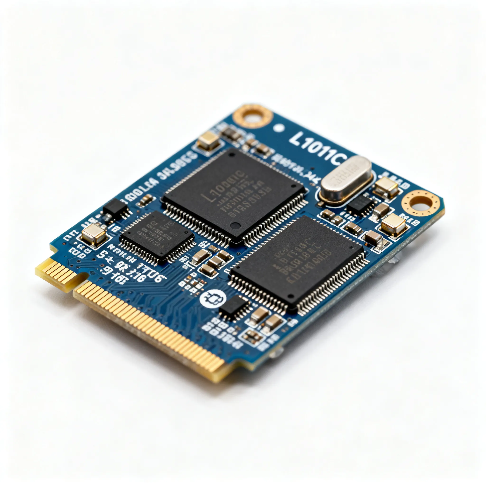
FSD200 in Offline LED Bulb Design: A Switching Power Supply Case Study
Expert guide on FSD200 in Offline LED Bulb Design: A Switching Power Supply Case Study. Technical specs, applications, sourcing tips for engineers and buyers.
Why the FSD200 Remains a Staple in Cost-Driven LED Bulb Designs
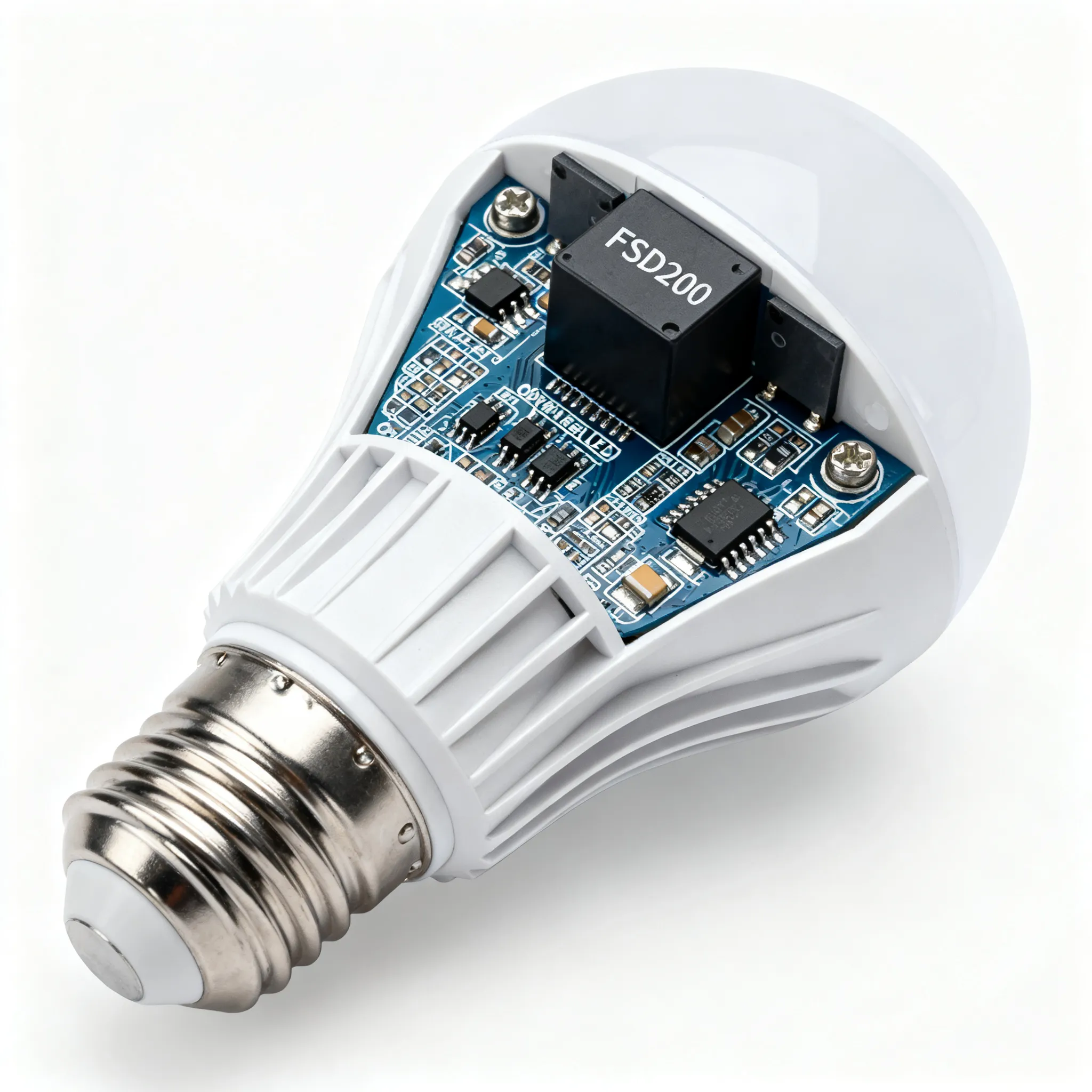
When you open a bargain LED bulb rated between 3 W and 7 W, there’s a good chance the tiny seven‑pin DIP package on the back of the PCB is a FSD200. This green‑mode Fairchild Power Switch (now part of the onsemi portfolio) has been turning up in offline flyback converters for nearly two decades. Its staying power isn’t accidental: the FSD200 combines a 700 V SenseFET, a fixed 134 kHz PWM controller, and a suite of protections in a single through‑hole package, all while keeping the external bill of materials to a bare minimum. For manufacturers who count every cent, that integration still translates into a winning cost structure.
Yet the FSD200 isn’t just a museum piece. Distributors continue to hold substantial inventory. Heisener lists 6,976 pieces in stock at the time of writing, and Jotrin Electronics confirms ready availability. These aren’t obsolete excesses being cleared; they reflect a steady demand from maintenance teams and cost‑conscious OEMs who value the proven reliability of a DIP‑7 power switch that can be hand‑soldered during prototyping or rework. For a 5 W LED lamp that needs to meet tight budget constraints, the FSD200 still checks every box: it starts up from a rectified 230 VAC line without a separate auxiliary winding, it enters burst mode at light loads to satisfy standby regulations, and its built‑in thermal shutdown protects the bulb when the heatsink gets too hot.
Of course, the lighting market has moved toward smaller, surface‑mount switchers with primary‑side regulation and ultra‑low standby. But for many non‑dimmable, fixed‑color bulbs sold in emerging markets, the FSD200 remains a practical, low‑risk choice. The following sections unpack what’s inside the part, how it stacks up against alternatives, and how to avoid the most common design and procurement pitfalls.
Inside the FSD200: Green-Mode PWM, Burst Operation, and Protections
The FSD200 is more than a high‑voltage MOSFET in a black epoxy block. Its internal block diagram reveals a fixed‑frequency PWM modulator, a current‑sense comparator, a leading‑edge blanking circuit, and a precise bandgap reference—all tied to the gate of a 700 V SenseFET. The controller operates at a tightly regulated 134 kHz, a frequency high enough to shrink the flyback transformer but low enough to keep switching losses manageable in a through‑hole package. The part’s “green mode” label comes from the burst‑mode operation that kicks in below approximately 0.5% of the maximum output power. In this mode, the internal oscillator toggles on and off in bursts, dramatically reducing switching losses and keeping the input power below 0.5 W at no load—a requirement for many energy‑efficiency standards.
On the protection side, the FSD200 integrates undervoltage lockout (UVLO) with hysteresis, which prevents the switch from attempting to start up when the input voltage is too low. The typical UVLO turn‑on threshold is 12 V, and the turn‑off threshold is 8 V, ensuring a clean start‑up sequence. An internal thermal shutdown sensor trips at approximately 140°C junction temperature, latching the device off until the power is cycled. This is particularly valuable in LED bulb designs where the driver PCB is often sandwiched between the LED board and the screw base, with limited airflow. The datasheet (available from Alldatasheet and Datasheetspdf) also specifies a cycle‑by‑cycle current limit of typically 0.58 A, which protects the internal SenseFET and the secondary rectifier against output shorts.
Table 1 – Key Electrical Parameters of the FSD200
| Parameter | Value/Range | Unit | Notes |
|---|---|---|---|
| Drain‑Source Breakdown Voltage | 700 | V | Sufficient for 230 VAC or 100/115 VAC with doubler |
| Switching Frequency | 134 ± 10% | kHz | Fixed, no external resistor |
| Maximum Duty Cycle | 67 | % | Typical, at full load |
| Current Limit (Peak) | 0.58 | A | Cycle‑by‑cycle; minimum 0.48 A |
| UVLO Turn‑on Threshold | 12 | V | Vcc rising |
| UVLO Turn‑off Threshold | 8 | V | Vcc falling |
| Burst‑mode Entry | ~0.5% of Pmax | — | Approx. 0.25 W output for a 7 W design |
| Thermal Shutdown | 140 | °C | Junction temperature; auto‑restart after power cycle |
| Standby Power (No Load) | < 0.5 | W | With proper transformer design |
| Package | DIP‑7 | — | Through‑hole, 300 mil wide |
These parameters set the boundaries for any LED driver design. The fixed 134 kHz frequency dictates the transformer core size and turns ratio. The current limit, combined with the 700 V rating, allows the FSD200 to handle the reflected voltage and leakage inductance spikes that are typical in a flyback topology. The built‑in burst mode, while helpful for standby, does introduce a design challenge for LED bulbs: the low‑frequency burst envelope can cause visible flicker if the output capacitor is too small. We’ll address that in the FAQ and design guidance sections.
FSD200 vs. Other Offline Switchers: Choosing the Right Fit for Your LED Driver
The FSD200 sits in a crowded field of offline switchers, and selecting the right one for your LED bulb design requires balancing power, standby, feedback complexity, and cost. The FSD200’s closest sibling, the FSD210, pushes the power envelope to about 10 W by increasing the current limit and duty cycle range. The FSDM311, a later generation from Fairchild/onsemi, offers a lower standby power and a pulse‑by‑pulse current limit that is more suited for modern energy regulations. Meanwhile, Power Integrations’ LinkSwitch‑TN2 family (e.g., LNK3204) provides a compact non‑isolated buck‑boost topology with primary‑side regulation, eliminating the optocoupler entirely. For isolated flyback designs, however, the FSD200 still holds its ground.
Table 2 compares the FSD200 with three alternatives that are frequently considered for offline LED driver applications. The data is drawn from the respective datasheets and product overviews, including Ovaga’s product page and the Elcodis datasheet listing.
Table 2 – Comparison of Offline Switchers for LED Bulb Flyback Designs
| Comparison Metric | FSD200 | FSD210 | FSDM311 | LinkSwitch‑TN2 (LNK3204) |
|---|---|---|---|---|
| Topology | Isolated flyback | Isolated flyback | Isolated flyback | Non‑isolated buck‑boost / flyback |
| Max. Output Power (230 VAC, open frame) | ~7 W | ~10 W | ~8 W | 4 W (buck‑boost) |
| Switching Frequency | 134 kHz | 134 kHz | 67 kHz | ~66 kHz (jitter) |
| Standby Power (No Load) | < 0.5 W | < 0.5 W | < 0.1 W | < 30 mW |
| Feedback Method | Optocoupler + TL431 | Optocoupler + TL431 | Optocoupler + TL431 | Primary‑side regulation (no optocoupler) |
| Package | DIP‑7 | DIP‑7 | DIP‑8 / SOP‑8 | SOT‑23‑3 / SO‑8 |
| Burst Mode | Yes, at ~0.5% load | Yes | Yes, with deeper burst | Yes, mode‑switching |
| Protection Features | UVLO, thermal shutdown, cycle‑by‑cycle current limit | Same + autorestart | Same + OLP, OVP | Thermal, current limit, auto‑restart |
| Typical Unit Cost (1k quant.) | Low | Moderate | Moderate | Low–moderate |
The choice becomes clear once you define the bulb’s isolation requirements. For a screw‑base LED bulb that must pass safety isolation between the mains and the LED heatsink, an isolated flyback with an optocoupler is the standard approach. Here, the FSD200 and FSD210 are nearly identical except for the output power ceiling. If you need 7 W or less, the FSD200 is the more economical pick. The FSDM311 offers a meaningful improvement in standby power, but its 67 kHz switching frequency often requires a larger transformer, which can be a problem in the tight confines of an A19 bulb. The LinkSwitch‑TN2 bypasses the optocoupler, but the non‑isolated topology demands a double‑isolated enclosure and is rarely used in direct‑retrofit bulbs. Thus, for the classic 5 W–7 W isolated LED driver, the FSD200 remains a pragmatic default.
Designing a Bulb with the FSD200: Transformer, Layout, and Procurement Pitfalls
Getting a reliable LED bulb out of the FSD200 is not just about copying the application circuit from the datasheet. The physical constraints of a bulb—the cylindrical PCB, the heat from the LEDs, and the need for a tall electrolytic capacitor—mean that every design choice must be deliberate. The following practical guidance comes from the experience of repairing and reverse‑engineering dozens of commercial bulbs, as well as from conversations with power‑supply engineers who have used the FSD200 in volume production.
Transformer selection: For a 5 W LED driver operating from 230 VAC, an EFD15 or EE16 core is the sweet spot. These cores are readily available, low‑profile, and can be wound automatically. A primary inductance of 1.2–1.5 mH, with a primary turn count of 100–120 turns of 0.15 mm enameled wire, yields a reflected voltage of around 100 V and keeps the peak drain voltage below 600 V even with a practical RCD snubber. The secondary turns are then calculated to deliver the desired LED string voltage—typically 20–30 V for a string of 6–9 LEDs in series. Table 3 provides a starting point for a 5 W design.
Table 3 – Recommended Transformer Parameters for a 5 W LED Driver with FSD200
| Parameter | Recommended Value | Comments |
|---|---|---|
| Core | EFD15 / EE16 (PC40 or equivalent) | Gapped for desired inductance |
| Primary Inductance (Lp) | 1.2–1.5 mH | Measured at 1 kHz, 0.1 V |
| Primary Turns (Np) | 100–120 | 0.15–0.18 mm wire, single layer |
| Secondary Turns (Ns) | 15–25 (for 25 V output) | 0.30–0.40 mm wire, triple‑insulated if safety required |
| Auxiliary Turns (Na) | 12–15 | Supplies Vcc to FSD200; use 0.12 mm wire |
| Leakage Inductance | < 5% of Lp | Critical for snubber dissipation |
| Snubber Type | RCD with 100 V TVS clamp | 1N4937 + 100 μF electrolytic; resistor 100 Ω/1 W |
After the transformer, the output capacitor is the next component that can make or break the design. The FSD200’s burst mode switches in packets of a few cycles at 134 kHz, producing a low‑frequency ripple component that can land in the 100 Hz–1 kHz range. If the output capacitor is too small, this ripple modulates the LED current and becomes visible as shimmer or flicker. A 470 μF low‑ESR electrolytic capacitor is a good starting point; for high‑CRI or photography‑grade bulbs, a 680 μF or even a 1000 μF capacitor, combined with a small LC post‑filter, may be necessary. Always test for flicker with a photodiode and oscilloscope, not just with the naked eye—perception varies widely.
Layout and thermal considerations: The DIP‑7 package of the FSD200 dissipates heat primarily through the PCB copper. Dedicate at least 2 cm² of copper pour on the drain pin and the ground pin, and consider using a 1.6 mm thick board with 2 oz copper. Keep the snubber diode and resistor close to the drain pin to minimize the loop area and reduce EMI. The electrolytic capacitors should be placed as far as possible from the LED load, but in a bulb, space is at a premium; a common compromise is to use a tall, slim capacitor and mount it horizontally, held in place with a dollop of silastic adhesive.
Procurement pitfalls: The longevity of the FSD200 on the market has made it a target for counterfeiters. Parts with poor marking quality, inconsistent on‑state resistance, or missing UVLO hysteresis are not uncommon in the spot market. To avoid field failures, source only from authorized distributors or reputable independent distributors with in‑house testing. Jotrin and Heisener are both known to stock genuine parts, and their inventory levels suggest that the FSD200 hasn’t yet slipped into the “hard‑to‑find” category. For new designs, however, it’s prudent to check the latest lifecycle status with onsemi and evaluate pin‑compatible alternatives like the FSDM311, which uses the same DIP‑7 footprint and offers a smoother migration path.
- Always buy from authorized sources or trusted independents; ask for a photo of the date code if ordering from a broker.
- Demand a sample lot and test the UVLO and current limit before committing to a production batch.
- Keep the transformer’s leakage inductance below 5% of primary inductance—otherwise the snubber will overheat and the EMI will be difficult to filter.
- Use a 100 μF or larger Vcc capacitor with a 16 V rating to ensure stable start‑up and immunity to burst‑mode dips.
- For designs that must meet 0.3 W standby, consider a pre‑load resistor or a secondary‑side bleeder, but be aware that this adds constant power dissipation.
FSD200 LED Bulb Design FAQ: Top Questions from Engineers and Buyers
Q: What is the maximum continuous output power I can get from the FSD200 in an LED bulb application?
A: In a typical isolated flyback design with adequate heatsinking, the FSD200 can deliver up to 7 W continuously. This limit is set by the internal current limit and the thermal dissipation of the DIP‑7 package. If you push beyond 7 W, the junction temperature will approach the 140°C shutdown threshold, especially in an enclosed bulb. For a 10 W design, the FSD210 is a drop‑in upgrade with a higher current limit, though it may require a larger core and different feedback compensation.
Q: Does the FSD200 require an optocoupler for constant‑current LED regulation?
A: Yes, the FSD200 relies on secondary‑side feedback through an optocoupler and a voltage reference (typically a TL431) to regulate the output. The IC itself does not have a primary‑side sensing pin; it compares the feedback voltage on its FB pin against an internal reference. While you can design a primary‑side regulated constant‑current circuit using an auxiliary winding and a current‑sense resistor, the accuracy is poor and varies with transformer coupling. For a stable LED current, an optocoupler is the reliable path.
Q: Will the burst mode operation cause visible flicker in LED bulbs at light load?
A: Burst mode can introduce a low‑frequency ripple component that may cause perceptible flicker if the output capacitor is too small. The FSD200 bursts in a pattern that can have a repetition rate of a few hundred hertz. A 470 μF electrolytic capacitor is usually sufficient to smooth this out for most applications, but for dimmable or high‑CRI bulbs, you may need to add a second LC filter stage or increase the output capacitance to 1000 μF. Always test the design with a flicker meter or a photodiode and oscilloscope, as visual inspection alone can miss marginal artifacts.
Q: What transformer core and turns ratio do you recommend for a 5 W LED driver with FSD200?
A: An EFD15 or EE16 core is ideal. A primary inductance of 1.2–1.5 mH, with a primary turns count of 100–120 turns, works well for a 230 VAC input. The secondary turns ratio should be chosen to deliver the required LED string voltage, typically 20–30 V. For a 25 V output, a secondary of 15–25 turns of 0.35 mm wire is a good starting point. Table 3 in the design guidance section provides a detailed set of parameters. The FSD200 datasheet also includes an application example that can be scaled to your specific LED load.
Q: Is the FSD200 still in active production, and what is the risk of obsolescence?
A: The FSD200 is an older Fairchild/onsemi part, and while onsemi has not formally announced its discontinuation, it is considered a mature product, and lead times can be unpredictable. Distributors such as Heisener and Jotrin still hold inventory, but for new designs, it’s wise to verify the current lifecycle status directly with onsemi. If you’re designing a new product, consider the pin‑compatible FSDM311, which offers similar functionality with lower standby power and a more modern process. The FSDM311 can be used in the same DIP‑7 footprint, allowing a seamless transition if the FSD200 becomes unavailable.
Conclusion: The FSD200 may not be the flashiest offline switcher, but it’s a trusted workhorse that has powered millions of LED bulbs. Its 700 V SenseFET, fixed 134 kHz PWM, and built‑in protections simplify the BOM and keep the driver cost competitive. For engineers who need to spin a 5 W–7 W isolated flyback converter quickly, and for buyers who want a reliable source of mature components, the FSD200 remains a solid option. For a mixed BOM or flexible MOQ, IC-Online offers a convenient platform to search for the FSD200 and complementary passives, helping you balance cost and availability without compromising on genuine parts.
References & Further Reading
- FSD200 Datasheet (PDF) – Fairchild Semiconductor
- FSD200 Datasheet – Green Mode Fairchild Power Switch
- FSD200 Datasheet Search – Alldatasheet
- FSD200 Product Overview – Ovaga Technologies
- FSD200 Inventory & Pricing – Heisener
- FSD200 Stock & Information – Jotrin Electronics
- FSD200 Datasheet & Specifications – Elcodis
- IC-Online – Electronic Components Sourcing Platform