

A 2026 Analysis of Inverting Op Amplifiers
The inverting amplifier remains a critical component in 2026. Its relevance is defined by precision and stability
The inverting amplifier remains a critical component in 2026. Its relevance is defined by precision and stability in high-performance analog signal processing. This op-amp finds a key application in automated systems and IoT sensor interfaces, ensuring a clean signal. The classic inverting op amplifier circuit provides a stable foundation for a predictable signal. This operational amplifier configuration is a cornerstone for reliable performance. The inverting amplifier is a fundamental circuit for modern electronics.
Key Takeaways
- The inverting amplifier is important for processing analog signals. It is stable and precise.
- A key feature of the inverting amplifier is the 'virtual ground.' This helps make circuits stable and reduces noise.
- Engineers must choose between gain and bandwidth. High gain means less bandwidth for the signal.
- The inverting amplifier is good for sensors that output current. It changes current signals into voltage signals.
- Future inverting amplifiers will be smaller and use less power. They will also use digital help to work better.
Core Principles of the Inverting Op Amplifier
Understanding the inverting amplifier begins with its foundational principles. While the design is classic, its application in 2026 demands a modern perspective on its behavior. This circuit configuration remains a go-to choice for engineers due to its inherent stability and predictable performance, which are direct results of its core design.
The Modern Operational Amplifier Refresher
The inverting amplifier is a simple yet powerful circuit. It consists of an operational amplifier and two resistors. The input signal is applied to the inverting input terminal (-) through an input resistor, Rin. A feedback resistor, Rf, connects the output terminal back to the same inverting input. The non-inverting input (+) is typically connected to ground.
The primary function of this inverting amplifier is to amplify and invert the input signal. The closed-loop gain is determined entirely by the ratio of the two resistors.
Gain Formula:
Vout = -Vin * (Rf / Rin)
The negative sign indicates the 180-degree phase inversion; a positive input voltage produces a negative output voltage. This behavior is controlled by negative feedback, where a portion of the output signal is fed back to the inverting input. This negative feedback mechanism is what gives the inverting amplifier its exceptional stability and gain precision. A core rule for an ideal op-amp is that no current flows into its input terminals.
However, modern designs must account for the differences between an ideal operational amplifier and a real-world 2026 op-amp.
| Parameter | Ideal Operational Amplifier | Real-World 2026 Operational Amplifier |
|---|---|---|
| Open-Loop Gain | Infinite | Finite (typically > 100,000) |
| Input Impedance | Infinite | Finite (differential and common-mode) |
| Bandwidth | Infinite | Finite (reduces at high frequencies) |
| Slew Rate | Infinite | Finite |
| Output Impedance | Zero | Non-zero (lowered by negative feedback) |
| Noise | Zero | Present |
| Input Current | Zero | Small, non-zero (due to biasing/leakage) |
Virtual Ground's Role in Precision Circuits
A key concept in the inverting op amplifier is the "virtual ground." Due to the high open-loop gain and negative feedback, the op-amp works to keep the voltage at the inverting input (V-) equal to the voltage at the non-inverting input (V+). Since V+ is often tied to ground (0V), the V- terminal is also held at 0V. It is a "virtual" ground because it is not physically connected to ground but behaves as if it were.
This virtual ground is critical for several reasons:
- Stability: It creates a stable and predictable node in the circuit. The input current from the signal source flows through
Rindirectly to the feedback path throughRf, not into the op-amp. - Noise Reduction: By holding the input at a constant potential, the inverting amplifier configuration helps minimize the effects of common-mode noise on the signal.
- Precision Converters: It makes the inverting amplifier an excellent current-to-voltage converter (trans-resistance amplifier). A current signal can be fed directly to the virtual ground node, and the output voltage becomes a precise, scaled representation of that input current.
For example, dedicated ICs like the Texas Instruments TLE2426 "Precision Virtual Ground" are designed to create a stable reference. However, even these components have limits. Driving a heavy load like headphones could cause the IC to shift its ground reference, introducing distortion. This highlights the importance of careful circuit design.
Note: Always consult op-amp datasheets to ensure stability when driving capacitive loads. Certain capacitance ranges can compromise the feedback loop and degrade the signal. The stability of the feedback is paramount for a clean signal.
Gain vs. Bandwidth in High-Speed Designs
In 2026, where high-speed data acquisition and communication are standard, the trade-off between gain and bandwidth is a central design consideration. Every operational amplifier has a fixed Gain-Bandwidth Product (GBWP). This value represents a fundamental limit on the op-amp's performance.
The relationship is simple: for a given inverting op amplifier, increasing the closed-loop gain will decrease the available bandwidth for the signal.
- An inverting amplifier with a low gain can process a wide range of signal frequencies.
- An inverting amplifier with a high gain will have a much narrower bandwidth, limiting its use to lower-frequency signals.
This trade-off is crucial. Using an inverting amplifier with too much gain for a high-frequency signal will result in attenuation and distortion, corrupting the signal integrity. Engineers must select an op-amp and a feedback network that provide the necessary gain while preserving the bandwidth required for the application's signal. The feedback resistors directly influence both the gain and the stability of the final circuit. This careful balance of gain, feedback, and bandwidth defines modern analog design.
Inverting vs. Non-Inverting: 2026 Use Cases
Choosing between an inverting and non-inverting operational amplifier configuration is a fundamental decision in modern analog design. The correct choice depends entirely on the specific application scenarios and performance goals. While both circuits amplify a signal, their inherent characteristics make them suitable for very different tasks, especially in the demanding electronics landscape of 2026.
The Inverting Amplifier in Sensor Interfaces
The inverting amplifier excels in modern sensor interface design. Its primary advantage lies in its virtual ground feature. Many advanced sensors do not output a simple voltage. Instead, they produce a current signal that is proportional to the physical quantity being measured.
Common current-output sensors include:
- Photodiodes: Used in optical data networks and medical imaging, they convert light into a very small current.
- Pressure Transducers: Found in industrial automation, these can output a current signal representing pressure levels.
- Accelerometers: Certain MEMS accelerometers provide a current output for motion detection in IoT devices.
For these application scenarios, the inverting amplifier is configured as a transimpedance amplifier (TIA). The current signal from the sensor is fed directly into the virtual ground node. Because this node is held at 0V, the circuit presents a near-zero impedance, allowing the sensor to operate with maximum linearity and speed. The operational amplifier then converts this input current into a stable output voltage. This makes the inverting amplifier an indispensable circuit for achieving a high-fidelity signal from current-source sensors.
Signal Integrity and Noise Immunity
Signal integrity is paramount in high-performance systems. The choice between configurations directly impacts noise and stability. Both the inverting and non-inverting amplifier amplify the op-amp's internal voltage noise. However, the inverting amplifier also introduces noise from its input and feedback resistors. Careful resistor selection is therefore critical to managing the overall noise performance.
A common question is which configuration offers more bandwidth. For the same noise gain, their bandwidths are quite similar. In practice, a non-inverting circuit might show slightly higher bandwidth for the same signal gain, but this must be verified. For example, a non-inverting sensor amplifier with a gain of 11 V/V and a 50 MHz GBW op-amp has an estimated bandwidth of 4.5 MHz. An inverting audio mixer with a noise gain of 3 and a 30 MHz GBW op-amp has a bandwidth closer to 10 MHz. This shows how gain and topology interact to define the final performance. The stability of the signal is also a key factor. The non-inverting amplifier generally has a better phase margin, making it more stable across a wider range of frequencies.
Use-Case Decision Matrix
To simplify the decision-making process, engineers can refer to a direct comparison of the two topologies. The ideal choice is always dictated by the requirements of the application. The following matrix breaks down the key differences for typical 2026 application scenarios.
| Characteristic | Inverting Amplifier | Non-Inverting Amplifier |
|---|---|---|
| Input Impedance | Set by the input resistor (Rin). Offers a predictable but relatively low input impedance. | Extremely high, approaching the op-amp's intrinsic input impedance. Does not load the source. |
| Gain | Can be less than, equal to, or greater than 1. Provides signal inversion (180° phase shift). | Must be greater than or equal to 1 (unity). The signal phase is preserved. |
| Stability | Generally stable, but feedback network can interact with load capacitance. | Often more stable with better phase margin, especially in unity-gain buffer configurations. |
| Ideal 2026 Applications | Current-to-Voltage Converters: Interfacing with photodiodes and pressure transducers. Audio Mixers: Summing multiple audio signals at the virtual ground node. Active Filters: Forms the basis for many filter designs due to predictable gain. | High-Impedance Buffers: Interfacing with high-output-impedance sensors or voltage sources. Preamplifiers: Buffering a weak voltage signal without loading it. System Integration: As a HiSilicon-designated solutions partner, Nova Technology Company (HK) Limited often leverages this topology in complex System-on-Chip (SoC) designs to buffer sensitive analog signals before they are processed by digital cores. |
Ultimately, the inverting op amplifier provides a stable, precise circuit for manipulating a signal when source impedance is not the primary concern. Its ability to create summing junctions and precise current-to-voltage converters secures its role in advanced analog systems. The non-inverting amplifier, by contrast, is the go-to choice for buffering and amplifying a voltage signal from a high-impedance source where preserving the signal integrity is the top priority.
Future Trajectory Beyond 2026
The inverting amplifier is not a static component. Its future is defined by deeper integration, radical efficiency, and digital enhancement. These trends ensure the classic inverting amplifier remains essential for next-generation electronics.
Trend 1: System-on-Chip (SoC) Integration
The move toward miniaturization places the inverting amplifier directly onto complex System-on-Chip (SoC) designs. This integration places sensitive analog circuits next to noisy digital logic. Engineers face significant challenges in maintaining signal integrity.
- Interference: Sensitive analog circuits like an inverting amplifier can be disrupted by noisy digital switching activity.
- Crosstalk: Noise can propagate through the shared silicon substrate, degrading the analog signal.
- Substrate noise coupling: Digital switching often induces noise into the substrate, which then couples into the analog circuit.
Successfully managing these issues is critical for creating compact, high-performance systems where the inverting amplifier handles analog signal processing tasks.
Trend 2: Ultra-Low Power for IoT Devices
The explosion of battery-powered IoT devices demands extreme power efficiency. The inverting amplifier is evolving to meet this need. Low-power precision op-amps now feature a supply current of less than 1mA.
- Ultra-low-power operational amplifiers for IoT are designed with quiescent currents in the microampere or even nanoampere range.
- This development is crucial for extending the battery life of devices like remote sensors.
- Manufacturers use advanced designs to minimize power consumption for each inverting amplifier.
A key strategy is duty cycling. This technique improves energy efficiency by turning components on and off. The inverting amplifier and sensor are powered down when not in use. This application of smart power management achieves significant energy savings.
| Power Mode | Typical Current Consumption |
|---|---|
| Continuous Conversion | 32 μA |
| Duty Cycling | 5 μA |
| Shutdown Mode | 0.5 μA |
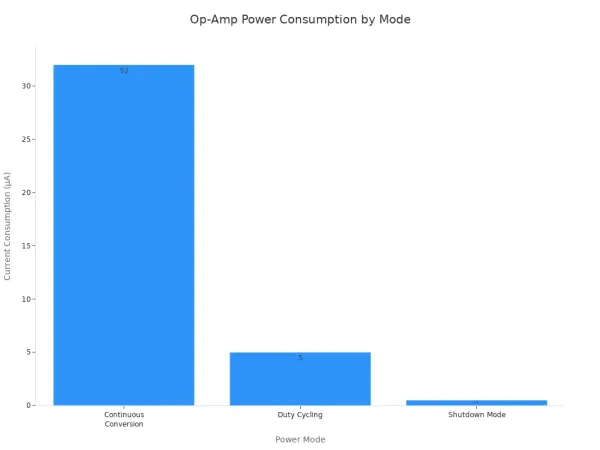
This approach ensures the signal conditioning process does not drain the battery, boosting overall system performance.
Trend 3: Digitally-Assisted Analog Performance
The future of the inverting amplifier involves a partnership between analog and digital domains. Digitally-assisted techniques use software to correct for real-world analog imperfections, enhancing signal quality. This approach improves the performance of an inverting amplifier.
- Digital Calibration: This provides automated adjustments for offset and gain errors in the signal.
- Adaptive Control Loops: These offer real-time compensation for changes in temperature or load.
Software calibration is a powerful method. It captures the offset voltage of the inverting amplifier during a calibration phase. A microcontroller then digitally subtracts this captured offset from the output signal. This is highly effective for correcting signal drift caused by environmental changes.
The inverting op amplifier remains a cornerstone of analog design in 2026. Its stability makes the inverting amplifier a precise tool for a clean signal. The future of this inverting amplifier is defined by key trends. These include deeper integration, ultra-low power consumption, and digitally-assisted techniques that enhance the analog signal. This evolution, noted in recent CMOS and digitalized circuit research, guarantees the inverting amplifier a place in next-gen electronics. The inverting amplifier is a key circuit for any quality signal.
Mastering this fundamental inverting amplifier is more important than ever. The modern op-amp and operational amplifier continue to evolve.
FAQ
Why is the virtual ground still important in 2026?
The virtual ground provides a stable 0V reference point at the inverting input. This feature is critical for creating precise current-to-voltage converters and stable summing amplifiers. These circuits are essential for modern sensor interfaces and complex audio systems.
Can an inverting amplifier have a gain of less than one?
Yes, it can. The gain is determined by the ratio of two resistors. If the feedback resistor (Rf) is smaller than the input resistor (Rin), the amplifier will attenuate the signal. This is useful for scaling large input voltages down to a usable range.
- Formula:
Gain = -Rf / Rin - Condition for Attenuation:
Rf < Rin
What is the main trade-off in high-speed op-amp design?
The primary trade-off is between gain and bandwidth. Increasing the circuit's gain reduces its available bandwidth. Engineers must balance these parameters. This ensures the op-amp can accurately process the entire frequency range of the input signal without distortion. ⚙️
When should I choose a non-inverting amplifier instead?
Choose a non-inverting amplifier when you need extremely high input impedance. This configuration is ideal for buffering signals from high-impedance sources. It prevents the amplifier from loading down the source, which preserves the original signal's integrity.


