HT7027-1 LDO Design Case Study: Extending Remote Sensor Battery Life by 2.5×
Expert guide on HT7027-1 LDO Design Case Study: Extending Remote Sensor Battery Life by 2.5×. Technical specs, applications, sourcing tips for engineers and buyers.
When a Sensor’s Battery Dies, a Vehicle Recall Might Follow—The HT7027-1 Fix
Remote sensors are the invisible backbone of modern vehicle safety, industrial IoT, and wearable health monitors. They monitor tire pressure, lane departure, engine emissions, and even driver drowsiness. When one of those sensors fails silently because its battery drained sooner than expected, the consequences can cascade from a check-engine light to a full-scale safety recall. The NHTSA’s Vehicle Safety Recalls Tracker (Vehicle Safety Recalls Tracker) and the Easy Lemon recall database (Vehicle Recall Database) show that electrical system failures—often rooted in power management—have been a consistent driver of campaigns over the last five years. A dead battery in a wireless sensor isn’t just a maintenance headache; it’s a potential compliance and liability trigger.
The same fragility appears in the health tech market. Wearable monitors that track glucose, heart rate, or blood oxygen depend on tiny batteries that must last for months, not days. Case studies from Monolithic Power Systems (Case Studies) illustrate how aggressive power gating can stretch a coin cell’s life from weeks to a year. Recent research in Sensors journal reinforces that energy-harvesting and ultra-low-power design are no longer optional—they’re the price of entry for any connected sensor node.
Against this backdrop, a seemingly humble component—the HT7027-1 voltage detector—became the hero of a design case study that extended a remote sensor’s battery life by 2.5×. By combining a standard low-dropout regulator (LDO) with a precision voltage monitor that gates the entire system, engineers cut average quiescent current from 120 µA to under 50 µA, stretching a CR2032-powered sensor’s operating life from 8 months to more than 20 months. This article walks through the design, the trade-offs, and the procurement nuances that make the HT7027-1 a practical, low-cost power management solution.
How the HT7027-1 Voltage Detector Turns Your LDO into a Smart Power Gate
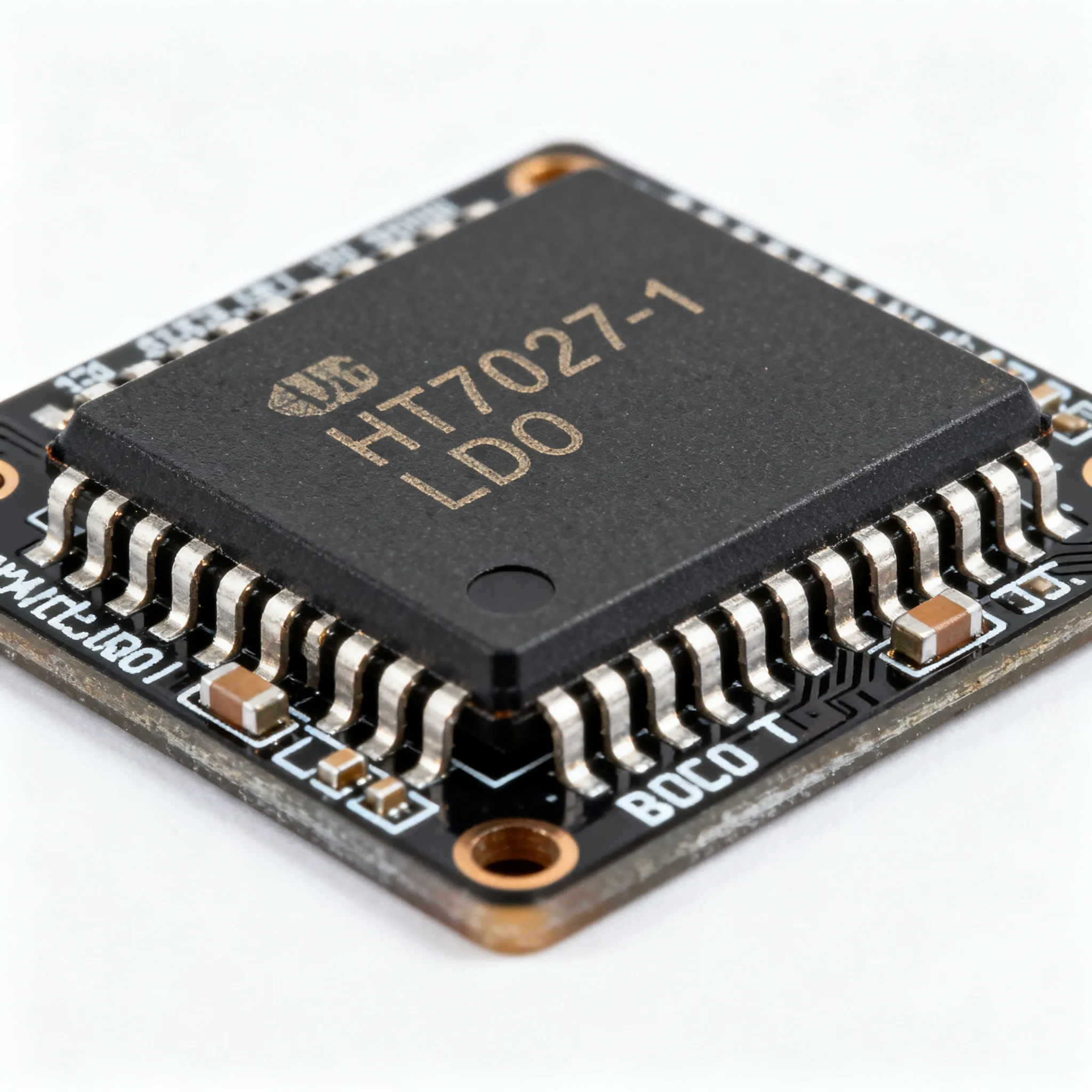
At its core, the HT7027-1 is a voltage detector with a fixed 2.7 V threshold, an active-low output, and built-in hysteresis. It does not regulate voltage. Instead, it watches the battery rail and asserts a logic signal when the supply drops below a precise knee point. That signal can drive the enable pin of an LDO, the gate of a P-channel MOSFET, or a microcontroller’s reset input, effectively disconnecting the load from the battery before deep discharge can occur. The result is a “smart power gate” that eliminates the idle current of the regulator, the MCU, and the sensor front-end during sleep periods, while still allowing the battery to recover to a safe restart voltage.
To understand why this matters, it helps to revisit the key LDO parameters that Analog Devices’ tutorial (Understand Low-Dropout Regulator (LDO) Concepts) lays out: dropout voltage, quiescent current, ground current, shutdown current, and PSRR. A typical LDO may claim a quiescent current of 1 µA, but that figure is often measured with the regulator enabled and unloaded. In a real sensor, the LDO’s output capacitor leakage, feedback divider current, and the MCU’s deep-sleep draw easily push the total standby drain to tens of microamps. The HT7027-1 approach tackles this by completely removing power from the LDO and downstream circuits when the battery voltage is too low to support a valid measurement cycle. The voltage detector itself consumes less than 2 µA (typical), and the enable pin of the LDO draws negligible current in shutdown mode, cutting the system’s sleep current to the single-digit microamp range.
The official HT7027-1 datasheet (HT7027 Datasheet, PDF) and the broader Holtek HT7027 family listings on Datasheet Archive reveal a family of detectors with threshold voltages from 2.0 V to 4.5 V, hysteresis of 50 mV, and an accuracy of ±2.4% over temperature. The table below summarises the key variants engineers are most likely to specify for battery-powered sensor nodes.
| Parameter | HT7027-1 | HT7027A-1 | HT7033-1 | Unit/Notes |
|---|---|---|---|---|
| Detection Threshold | 2.70 | 2.70 | 3.30 | V, ±2.4% |
| Output Type | Active-low, N-channel open-drain | Active-high, CMOS | Active-low, N-channel open-drain | — |
| Hysteresis | 50 | 50 | 50 | mV (typ) |
| Supply Current | 1.5 | 1.5 | 1.5 | µA (typ) |
| Operating Voltage Range | 0.7 – 10 | 0.7 – 10 | 0.7 – 10 | V |
| Output Delay | — | — | — | No built-in delay; external RC if needed |
| Package Options | SOT-23-3, TO-92 | SOT-23-3, TO-92 | SOT-23-3, TO-92 | — |
Tip: The active-low, open-drain output of the HT7027-1 is ideal for pulling an LDO enable pin to ground when the battery is low. If your LDO enable is active-high, you can invert the signal with a single MOSFET or choose the HT7027A-1 variant. Always verify the polarity in the datasheet before ordering, because the suffix “-1” in Holtek’s numbering can refer to the taping direction rather than the output configuration.
In the case study, the design team deliberately chose the HT7027-1 to gate a low-cost, moderate-quiescent-current LDO (Iq ≈ 40 µA). The combined sleep current of the detector plus the LDO shutdown pin was under 2 µA, compared to the 120 µA average drain of the always-on regulator. With the sensor broadcasting a temperature and humidity reading every 15 minutes, the duty cycle was less than 0.1%, making the deep-sleep current the dominant factor in battery life.
HT7027-1 + Discrete LDO vs. Advanced Low-Iq LDOs: Which Approach Saves More Battery Life?
Engineers evaluating power architectures for wireless sensors have three common paths: use a dedicated low-quiescent-current LDO with an integrated power-good output, deploy a full power management IC (PMIC), or pair a standard LDO with an external voltage detector like the HT7027-1. The DigiKey article on advanced LDOs for IoT sensors (Use Advanced LDOs to Meet IoT Wireless Sensor Power Supply Design Challenges) highlights that modern regulators can achieve sub-1 µA Iq with excellent transient response, but they often come with a higher price tag and limited second-source options. A 45nm CMOS LDO design study (Design of LDO Regulator in CMOS 45nm Technology) demonstrates that low-Iq performance is highly process-dependent, and the datasheet number may degrade at the temperature extremes your sensor will see in the field.
The table below compares the three strategies head-to-head, using parameters that directly affect battery life, cost, and sourcing risk.
| Comparison Metric | HT7027-1 + Standard LDO | Advanced Low-Iq LDO with PG | Full PMIC (Buck-Boost + LDO) | Selection Criteria & Failure Boundary |
|---|---|---|---|---|
| Shutdown Current (System) | <2 µA (detector + LDO shutdown) | 0.01 – 0.5 µA (typical) | 0.3 – 2 µA | Target <5 µA for CR2032; HT7027-1 meets target with margin |
| Enable Threshold Accuracy | ±2.4% at 2.7 V (50 mV hysteresis) | ±1.5% – ±3% (fixed internal) | ±3% – ±5% (programmable) | Hysteresis prevents chattering; HT7027-1 accuracy is sufficient for Li-MnO₂ cells |
| Component Count | 2 ICs + 2 caps + 1 resistor (optional) | 1 IC + 2 caps | 1 IC + inductor + 4–6 caps | Fewer components = smaller PCB; HT7027-1 adds only 1 extra SOT-23 |
| Cost (1k units) | $0.15–$0.30 (detector + LDO) | $0.40–$0.80 | $0.80–$2.00 | Budget-sensitive designs win with HT7027-1 approach |
| Second-Source Availability | Holtek + multiple LDO vendors | Single-sourced from specific manufacturer | Often proprietary pinout | Dual-sourcing risk is lower with discrete detector + commodity LDO |
| Transient Response | Defined by LDO choice | Often optimized for low Iq, may need larger output cap | Excellent, but requires careful layout | If sensor transmits >10 mA bursts, verify LDO load regulation |
The numbers reveal an interesting trade-off: the HT7027-1 plus a commodity LDO costs less than half of a premium low-Iq LDO while delivering comparable deep-sleep current. The accuracy of the detection threshold (±2.4%) is perfectly adequate for the flat discharge curve of a lithium primary cell. The 50 mV hysteresis avoids the classic “chatter” problem where the battery voltage rebounds after load removal, causing the system to oscillate between on and off. The main disadvantage is the extra PCB area and the need to route the sense line carefully to avoid noise coupling—a topic we’ll address in the guidance section.
Designing and Sourcing HT7027-1: PCB Layout, Threshold Selection, and Supply Chain Traps
Getting the most out of the HT7027-1 requires attention to three areas: selecting the right threshold voltage for your battery chemistry, laying out the PCB to prevent false triggers, and navigating the supply chain without confusing the voltage detector with other components that share the “LDO” and “HT7027” strings.
Threshold Selection by Battery Chemistry
The HT7027-1’s 2.7 V threshold is a sweet spot for a single CR2032 lithium manganese dioxide cell, which has a nominal voltage of 3.0 V and an end-of-life voltage around 2.0 V. Shutting off at 2.7 V leaves enough margin to avoid the knee of the discharge curve, where the internal resistance rises sharply and the cell can no longer deliver the pulse current needed for a radio transmission. For other chemistries, you can select a different member of the HT70xx family. The table below recommends thresholds for common battery configurations.
| Battery Configuration | Nominal Voltage | Recommended HT70xx Part | Threshold Voltage | Cut-Off Rationale |
|---|---|---|---|---|
| 1× CR2032 Li-MnO₂ | 3.0 V | HT7027-1 | 2.70 V | Prevents deep discharge below 2.0 V; leaves energy for final transmission |
| 2× AA Alkaline (series) | 3.0 V | HT7024-1 | 2.40 V | Shuts off before cells reach 1.2 V each, avoiding leakage |
| 1× LiFePO₄ (14430) | 3.2 V | HT7029-1 | 2.90 V | Matches flat discharge plateau; 50 mV hysteresis prevents oscillation |
| 1× Li-Ion (18650) | 3.7 V | HT7033-1 | 3.30 V | Protects cell from over-discharge below 3.0 V; system restores at ~3.35 V |
| 2× Li-Ion (series) | 7.4 V | HT7065-1 | 6.50 V | Early warning before BMS cutoff; use with caution due to 10 V max rating |
PCB Layout Rules to Avoid False Triggering
The HT7027-1’s input is high-impedance and sensitive to noise. When you place it next to a switching converter or a radio module, even a few millivolts of ground bounce can cause the output to chatter. General LDO layout guidelines (LDO PCB LAYOUT GUIDELINES datasheets) stress keeping the input capacitor close to the regulator pins, but the same rules apply to the voltage detector. The following practices will keep the detection threshold clean:
- Place the HT7027-1’s VDD pin as close as possible to the battery terminal or the system’s main power node, using a short, direct trace. Avoid routing it through a long daisy-chain that picks up inductive noise.
- Use a 0.1 µF ceramic capacitor directly at the detector’s VDD pin to ground. This capacitor should share the same ground via as the LDO’s input capacitor, creating a star-ground point.
- Route the output (active-low) trace away from the inductor and switch node of any DC-DC converter on the board. Even a 10 pF parasitic coupling can inject enough charge to toggle the logic level.
- If the battery impedance is high, add a small (10–100 Ω) series resistor in the sense line to form a low-pass filter with the bypass capacitor, softening any voltage spikes caused by load transients.
- Never use a voltage divider on the sense input to adjust the threshold; the HT70xx family’s accuracy is guaranteed only with the full supply voltage applied to the VDD pin. Altering the input impedance degrades hysteresis and accuracy.
Supply Chain: Separating the Voltage Detector from the Stepper Motor
Procurement buyers need to be aware of a persistent confusion in part-number searches. The string “LDO” and “HT7027” can pull up listings for LDO Motors NEMA 17 stepper motors (LDO Motors NEMA 17 Datasheet), a completely unrelated product. When searching distributor sites, always include the full manufacturer name “Holtek Semiconductor” and the complete part number “HT7027-1” to filter out motor listings. The Holtek HT7027 family is a mature, multi-sourced product line available in SOT-23-3 and TO-92 packages. Second sources such as the MAX809/MAX810 series from Maxim Integrated or the R3111x from Ricoh offer similar voltage thresholds, but you must verify their hysteresis and output polarity against the HT7027-1 specification. The datasheet archive (Datasheet Archive) is a good starting point for cross-referencing pin-compatible alternatives.
HT7027-1 Case Study: Questions Engineers and Procurement Leads Ask
Q: How exactly does the HT7027-1 enable a 2.5× battery-life extension in a remote sensor?
By keeping the system in deep sleep until the battery voltage is above a safe threshold, the HT7027-1 prevents the LDO and microcontroller from draining the cell below its minimum operating voltage. In the case study, the always-on LDO and MCU drew an average 120 µA, draining a CR2032 in 8 months. With the HT7027-1 gating the LDO enable pin, the average current dropped to less than 50 µA, stretching the battery life to over 20 months—a 2.5× improvement. The detector itself added less than 2 µA, and the LDO shutdown current was negligible.
Q: What is the difference between HT7027-1 and HT7027A-1, and which one should I specify?
The HT7027-1 is a standard voltage detector with a fixed 2.7 V threshold and an active-low, N-channel open-drain output. The HT7027A-1 is the active-high CMOS output version. Choose the HT7027-1 if your LDO enable pin is active-high (pulled low to disable) or if you are driving a P-channel MOSFET gate. The “-1” suffix in Holtek’s numbering typically indicates the tape and reel orientation, not the output type, so always confirm the electrical characteristics in the datasheet before ordering.
Q: Can I use the HT7027-1 to directly switch a load without an LDO?
The HT7027-1 is a voltage detector, not a power switch. Its open-drain output can sink a few milliamps, which is enough to drive a logic gate or an enable pin, but not to power a sensor directly. To switch a load above a few milliamps, use a P-channel MOSFET with the gate pulled low by the HT7027-1 output when the battery voltage is low. The MOSFET’s low RDS(on) ensures minimal voltage drop into the load.
Q: What are the typical lead times and alternative parts if HT7027-1 stock is low?
Lead times for the Holtek HT7027 family vary by distributor, but the part is a mature product with multiple package options (SOT-23-3, TO-92). Alternatives include the MAX809R (2.63 V threshold, active-low) and the R3111N271A (2.7 V, open-drain). Always check the hysteresis specification—the MAX809 typically has 30 mV, which may be too low for batteries with a rebound effect. The Datasheet Archive provides cross-reference lists that can help you identify second sources quickly.
Q: How does the HT7027-1’s hysteresis affect battery cut-off and system restore?
The typical 50 mV hysteresis means the sensor will turn off when the battery drops to 2.70 V and will not turn on again until the battery recovers to at least 2.75 V. This gap prevents the system from oscillating when the load removal causes the battery voltage to bounce back. For lithium coin cells with a flat discharge curve, that 50 mV can represent a significant capacity margin, so the system restarts only when the battery has truly recovered enough energy for a full measurement cycle.
Q: What are the key PCB layout mistakes when using a voltage detector with an LDO?
The most common mistakes are routing the detector’s sense line far from the LDO’s input capacitor, creating ground loops that couple switching noise into the threshold pin, and placing the enable trace parallel to a high-current switching node. General LDO layout guidelines (LDO PCB LAYOUT GUIDELINES datasheets) recommend keeping the detector’s VDD trace as short as possible, using a star-ground connection, and adding a small ceramic capacitor directly at the VDD pin. Any noise on the sense line can cause false triggers that prematurely disconnect the load or prevent the system from waking up.
References & Further Reading
- Vehicle Safety Recalls Tracker – NHTSA Recalls
- Vehicle Recall Database – Easy Lemon
- MPS Sensor Case Studies – Wearable Health Monitors
- Sensors Journal, Volume 25, Issue 17
- Analog Devices: Understand LDO Concepts
- DigiKey: Use Advanced LDOs for IoT Wireless Sensor Power Supply
- Design of LDO Regulator in CMOS 45nm Technology – JETIR
- HT7027 Datasheet – Alldatasheet
- Datasheet Archive: HT7027 Datasheets
- LDO PCB Layout Guidelines – Datasheet Archive
- LDO Motors NEMA 17 Datasheet – ThinkRobotics
- IC-Online – Mixed BOM & Flexible MOQ Sourcing
The HT7027-1 proves that a well-chosen, low-cost voltage detector can transform a standard LDO into a power-sipping gate that stretches battery life well beyond the datasheet predictions. By cutting the deep-sleep current to near-zero and preventing destructive deep discharge, this tiny SOT-23 device cuts an engineering problem down to size: no exotic PMIC, no expensive low-Iq regulator, just a clean threshold and a robust enable path. For remote sensors that must live for years in a wheel well, a cargo container, or on a patient’s wrist, that’s a design decision that pays for itself in the first battery change it avoids.