

Potential Transformers for Safe Voltage Monitoring
A potential transformer ensures safety in power systems by reducing hazardous high voltages. This device steps dow
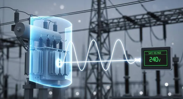
A potential transformer ensures safety in power systems by reducing hazardous high voltages. This device steps down thousands of volts to a standardized, safe level for voltage measurement. A potential transformer provides safety through two key functions: voltage reduction and complete electrical isolation.
Safety Note: International standards like EN 61010 define voltages above 30 Vrms or 60 VDC as dangerous, which is why stepping them down is critical for operator safety.
Think of a potential transformer as a "voltage telescope." It lets you safely observe a powerful electrical source from a secure distance.
Key Takeaways
- Potential transformers make high voltages safe to measure. They reduce dangerous electricity to a lower, usable level.
- These transformers keep high voltage away from people and equipment. They create a safe barrier.
- Potential transformers help power systems work well. They allow for accurate voltage checks and quick fault detection.
- There are different types of potential transformers. Some are for accurate billing, and others are for protecting the system during problems.
What is a Potential Transformer and How it Works
A potential transformer is a type of instrument transformer designed for one specific job: voltage measurement. Often called a voltage transformer (VT), its role is to create a precise, scaled-down replica of the voltage on a high-voltage line. This is different from its cousin, the current transformer, which measures current. To do its job correctly, a potential transformer is always connected in parallel with the circuit it is monitoring. This connection allows it to sample the voltage of the power system without interrupting the flow of power.
The device provides a safe and practical way to feed voltage signals to meters, relays, and other control equipment. These instruments are not designed to handle thousands of volts directly. The potential transformer bridges this gap, making high-voltage monitoring possible.
Voltage Step-Down for Safe Measurement
The core function of a potential transformer relies on a principle called electromagnetic induction, first discovered by Michael Faraday. The process works like this:
- Primary Winding: The potential transformer has a primary coil with many turns of wire. This coil connects directly to the high-voltage line. An alternating current (AC) from the power line flows through this winding.
- Magnetic Field: This AC current generates a changing magnetic field in the transformer's iron core. The core, made of a ferromagnetic material, concentrates this magnetic field and channels it efficiently. Transformers cannot work with direct current (DC) because DC does not produce the changing magnetic field needed for induction.
- Secondary Winding: A secondary coil with far fewer turns is wound around the same iron core. The fluctuating magnetic field from the core passes through this secondary coil, inducing a much lower voltage in it.
The ratio of turns between the primary and secondary windings determines the exact voltage reduction. For instance, a high voltage potential transformer with a 100:1 turn ratio will reduce 10,000 volts on its primary side to just 100 volts on its secondary side. This predictable relationship allows for highly accurate voltage readings.
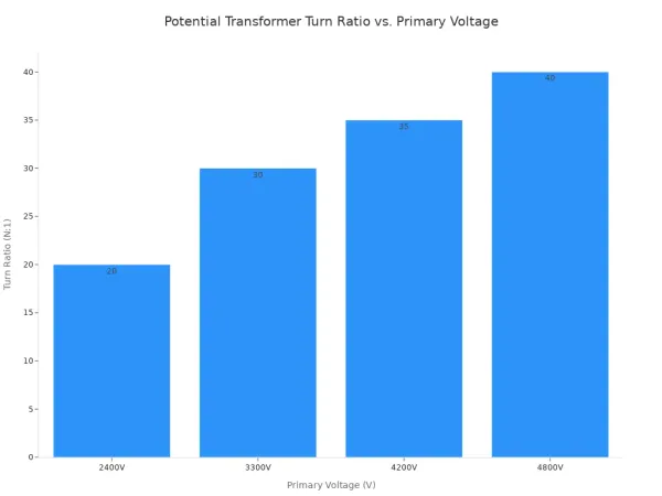
Here are some typical turn ratios for a potential transformer in medium-voltage applications:
| PT Class | Primary Voltage (V) | Secondary Voltage (V) | Turn Ratio |
|---|---|---|---|
| 5kV Indoor | 2400 | 120 | 20:1 |
| 5kV Indoor | 4200 | 120 | 35:1 |
| 5kV Indoor | 4800 | 120 | 40:1 |
| 5kV Outdoor | 3300 | 110 | 30:1 |
For a low voltage potential transformer, the ratio might be much smaller, but the principle remains the same. However, accuracy depends on more than just the turn ratio. The electrical load connected to the secondary winding, known as the "burden," also affects performance. Exceeding the rated burden can cause the voltage transformer to give inaccurate readings. Therefore, the burden must stay within the range specified by the manufacturer to ensure the instrument transformer operates correctly.
Electrical Isolation as a Protective Barrier
Beyond stepping down voltage, a potential transformer provides another critical safety feature: electrical isolation. There is no direct electrical connection between the high-voltage primary winding and the low-voltage secondary winding. They are linked only by the magnetic field within the iron core.
This separation creates a physical protective barrier. It ensures that dangerous high voltages from the main power line cannot cross over to the measurement equipment or endanger personnel.
Safety Tip 📝 The parallel connection of a voltage transformer is essential for both safety and accuracy. This setup ensures the device only samples the line's voltage, protecting both the measuring instruments and the operators from the immense power flowing through the main circuit.
This isolation is crucial for several reasons:
- It allows for accurate voltage readings without drawing significant power from the main line.
- It protects low-voltage measuring devices from being destroyed by high voltage.
- Most importantly, it guarantees the safety of engineers and technicians working with the monitoring equipment.
In modern power systems, the combination of voltage reduction and electrical isolation makes the potential transformer an indispensable tool for safe and reliable operation.
Core Components for Safety and Accuracy

The reliability of a potential transformer depends on the quality of its internal components. The design of its windings, core, and protective systems work together to ensure both safety and precision in demanding electrical environments.
Windings and Core Construction
The core and windings form the operational heart of a potential transformer. The primary winding has a large number of turns and connects to the high-voltage line. The secondary winding has far fewer turns and is wound closer to the core. This construction physically separates the high and low voltage circuits.
The core itself is made from materials with special magnetic properties. Common choices include:
- Silicon Steel: A cost-effective material used in many standard power and distribution transformers.
- Amorphous and Nanocrystalline Alloys: Advanced materials that offer very low energy loss and high efficiency, ideal for modern power systems.
For applications demanding the highest precision, such as laboratory instruments, manufacturers use nickel-iron alloys like Permalloy. An 80% nickel-iron alloy, often called Mumetal, is used to build high-accuracy current transformer cores. Its superior magnetic permeability helps prevent core saturation. Saturation occurs when the core cannot handle the magnetic field, leading to distorted signals, heat buildup, and a failure to produce accurate voltage readings.
Insulation and Grounding Mechanisms
Insulation and grounding are the primary safety features of a potential transformer. Insulation creates a physical barrier that prevents electricity from escaping its intended path. The materials used depend on the transformer type. Dry-type transformers often use solid materials like epoxy or polyester resin. Oil-filled transformers use dielectric oil as both an insulator and a coolant. The windings themselves are often coated in varnish and separated by paper.
Grounding provides a safe path for electrical faults. For safety, one terminal of the secondary winding is always connected directly to the earth.
Safety First 🛡️ This ground connection ensures that the secondary circuit remains at a low potential relative to the ground. It protects technicians and connected equipment from dangerous voltages if an insulation failure were to occur between the primary and secondary windings.
Proper grounding is a non-negotiable step for the safe operation of power systems. It turns the potential transformer into a truly secure buffer between hazardous voltages and the people who monitor them.
Types of Potential Transformers and Their Applications
Not all potential transformers are created equal. The specific job they need to perform—whether for billing or for emergency protection—determines their design. The main types of potential transformers are categorized by their internal construction and intended application in power systems.
Metering and Protection PTs
The two most common classes of this instrument transformer are built for either metering or protection.
- Metering PTs: A measuring potential transformer is designed for one thing: extreme accuracy. These devices provide precise voltage data for energy billing and power quality analysis. Their core is designed to operate with minimal error under normal conditions.
- Protection PTs: This type of voltage transformer is built for reliability during emergencies. It feeds voltage signals to protective relays. If it detects an overvoltage, the relay can trip a circuit breaker to prevent damage. For example, distance relays use voltage data from a potential transformer and current data from a current transformer to detect faults on transmission lines.
The core design of these two types is fundamentally different to meet their distinct goals.
| Feature | Protection PT | Metering PT |
|---|---|---|
| Primary Goal | Rapid response and overload resistance | High accuracy with minimal error |
| Overvoltage Behavior | Triggers relays when voltage exceeds set limits | Prioritizes accurate voltage readings within its range |
| Accuracy Class | Less precise (e.g., 3P, 6P) | Highly precise (e.g., 0.1, 0.2, 0.5) |
The Future is Smart 💡 Modern protection systems rely on more than just the transformer. The signals are processed by advanced electronics. Companies like Nova Technology Company (HK) Limited, a HiSilicon-designated solutions partner, provide the sophisticated chip-level solutions and system integration needed to build these smart relays. Their ICs enhance the speed and reliability of voltage measurement, making power systems safer.
Capacitive Voltage Transformers (CVTs)
For extra-high voltage (EHV) systems (110kV and above), traditional electromagnetic potential transformers become too large and expensive. This is where the Capacitive Voltage Transformer (CVT) comes in.
A CVT uses a series of capacitors to create a "capacitor divider." This divider first steps down the extremely high voltage to a more manageable intermediate level. Then, a small, conventional voltage transformer inside the CVT reduces it again to the standard secondary voltage. This two-stage process makes CVTs much more compact and cost-effective for EHV applications.
| Transformer Type | Common Applications |
|---|---|
| Electromagnetic PTs | Substations, industrial power, low-to-medium voltage grids |
| Capacitive PTs (CVTs) | High-voltage transmission, large-scale EHV installations |
However, CVTs have limitations. Their internal components can create voltage transients during a line fault, which may affect the performance of some high-speed protective relays.
A potential transformer is a fundamental safety device. It makes high-voltage power systems manageable and transparent. These instruments deliver safety in three primary ways:
- Stepping down dangerous voltages to a safe, standardized level.
- Providing complete electrical isolation between the high-voltage line and monitoring equipment.
- Enabling automated protective relays that rapidly isolate faults, ensuring minimal disruption to power systems.
Ultimately, the potential transformer is a non-negotiable component for reliable operation, bridging the critical gap between hazardous voltages and the need for precise monitoring.
FAQ
Why is a potential transformer connected in parallel?
A potential transformer connects in parallel to sample the line's voltage. This setup allows it to measure voltage without interrupting the main power flow. It ensures the PT accurately mirrors the system's voltage level for monitoring equipment.
Can a potential transformer work with DC voltage?
No, a potential transformer cannot work with DC voltage. Transformers require a changing magnetic field to induce voltage in the secondary coil. DC provides a constant current, which does not create the necessary changing field for the transformer to operate.
What is the "burden" of a potential transformer?
The "burden" is the total electrical load connected to the PT's secondary winding. This includes meters and relays. Exceeding the rated burden can cause inaccurate voltage readings. The burden must stay within the manufacturer's specified limits for proper performance.
Quick Tip 💡 Unlike a Current Transformer (CT), the secondary of a Potential Transformer (PT) can be safely left open-circuited. It will not create a hazardous voltage. However, the monitoring instruments will stop receiving data.


