How the SMDJ70CA TVS Diode Protects Automotive CAN Bus in Harsh Environments: A Case Study
Expert guide on How the SMDJ70CA TVS Diode Protects Automotive CAN Bus in Harsh Environments: A Case Study. Technical specs, applications, sourcing tips for engineers and buyers.
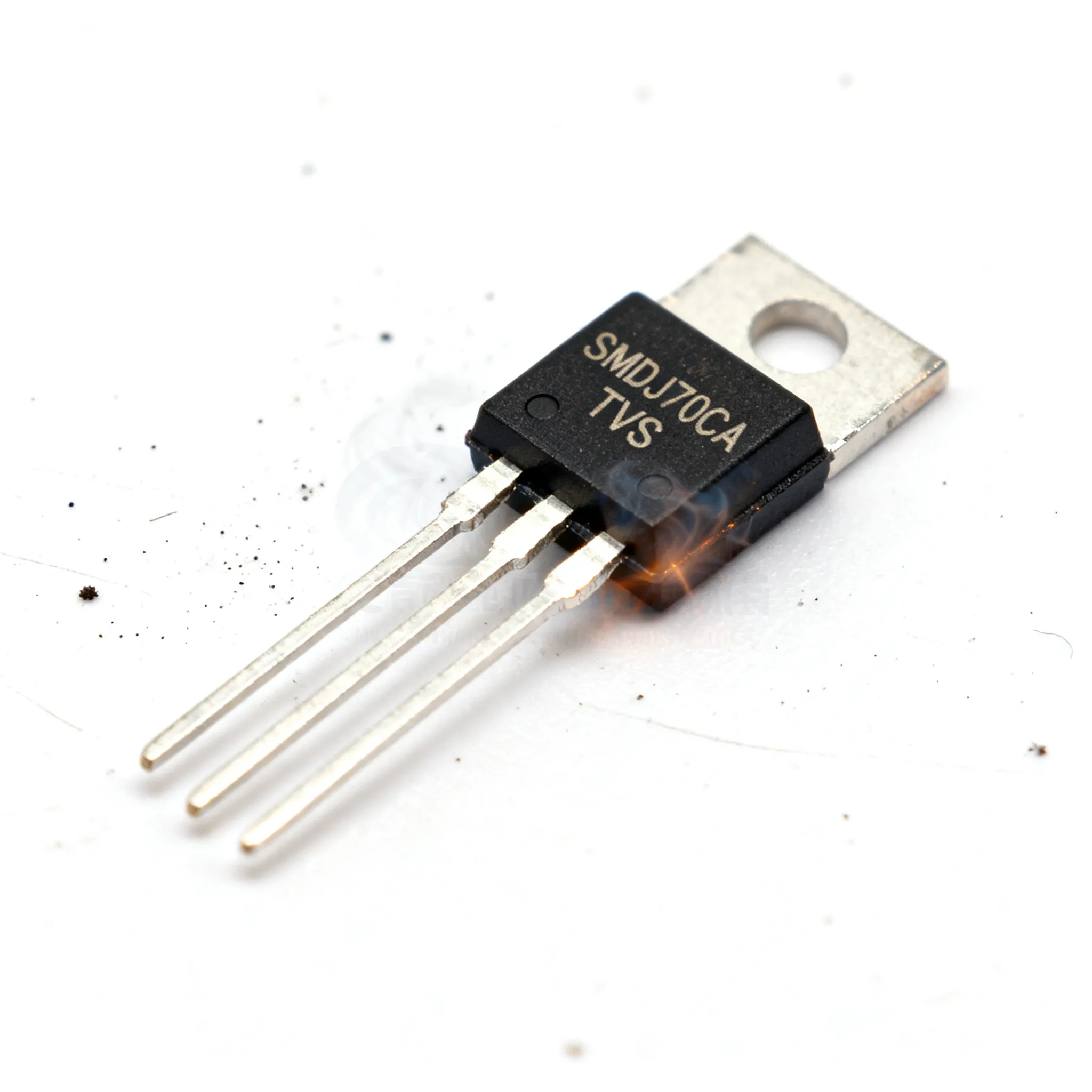
When a 24 V truck ECU resets mid-corner because a load-dump spike punched through its CAN transceiver, the root cause is rarely the microcontroller or the software. It’s the missing or undersized transient voltage suppressor. For a Tier‑1 supplier designing a next‑generation engine control module for a commercial vehicle platform, the difference between a 600 W TVS and a 3000 W device like the SMDJ70CA isn’t a safety factor—it’s the line between a five‑year warranty and a field recall. This case study walks through why the SMDJ70CA became the front‑line protection device on that ECU’s CAN bus, how its bidirectional clamping maps to the differential pair, and what engineers and buyers need to know to specify and source it without surprises.
Why a 3 kW TVS Diode in a DO-214AB Package Is the First Line of Defense for CAN Bus
Automotive CAN networks live in an electrically brutal neighborhood. A single wiring harness bundles the CAN_H and CAN_L twisted pair alongside ignition coils, injector solenoids, and brushed DC motors. Every inductive kick, every load‑dump event from a failing alternator, and every electrostatic discharge from a technician’s finger finds a path onto those differential lines. The CAN transceiver—often a standalone IC or integrated into a system basis chip—is rated for absolute maximum voltages of ±40 V or ±58 V depending on the generation. A raw load‑dump pulse on a 24 V truck can easily exceed 100 V for tens of milliseconds, well beyond what the transceiver’s internal ESD cells can absorb.
The industry’s accepted design practice, documented in application notes from ON Semiconductor (now onsemi) and reinforced by the Digi‑Key article on TVS diode protection for CAN bus, is to place a bidirectional TVS diode directly across the CAN_H and CAN_L lines at the connector entry point. The device must remain invisible during normal operation—its reverse standoff voltage must sit comfortably above the maximum continuous bus voltage—yet snap into conduction within nanoseconds when a transient arrives. The Mouser TVS selection guidelines for CAN bus stress that the peak pulse power rating must match the worst‑case transient energy, not the average. That’s where the 3000 W rating of the SMDJ70CA stops being a nice‑to‑have and becomes a hard requirement.
In our case study, the ECU was destined for a 24 V heavy‑duty truck with a 28 V alternator setpoint and occasional jump‑start voltages reaching 32 V. The CAN transceiver was a modern 5 V device with ±58 V fault tolerance. The design team initially evaluated a 600 W TVS in an SMB package, but thermal modeling under repetitive 10/1000 µs pulses showed the junction temperature would exceed 150 °C after three successive load‑dump events. The DO‑214AB (SMC) package of the SMDJ70CA provided a larger copper slug and a 3000 W peak pulse power rating at 10/1000 µs, giving enough headroom to survive the ISO 7637‑2 pulse 5a (load dump) without degradation. This wasn’t over‑engineering; it was the minimum viable protection after derating for ambient temperature under the hood.
Inside the SMDJ70CA: Bidirectional Clamping from 70 V Standoff to 113 V
A bidirectional TVS diode is essentially two avalanche diodes fabricated back‑to‑back on a single die. When the voltage across its terminals exceeds the breakdown voltage in either polarity, the device avalanches and shunts current, clamping the voltage to a safe level. For the CAN bus, this bidirectional behavior is critical because the differential pair can experience positive transients on CAN_H and negative transients on CAN_L simultaneously. A single bidirectional device placed between the two lines protects both polarities with one component, saving board space and cost.
The SMDJ70CA is built on a silicon avalanche technology that delivers a tight breakdown window and low dynamic resistance. Its key specifications, drawn from the Eaton SMDJ series datasheet and distributor listings, are summarized below.
| Parameter | Value | Unit / Notes |
|---|---|---|
| Reverse Stand‑Off Voltage (VRWM) | 70 | V – maximum DC voltage where diode remains off |
| Breakdown Voltage Min (VBR) | 77.8 | V – at 1 mA test current |
| Breakdown Voltage Max (VBR) | 86 | V – upper limit before conduction |
| Clamping Voltage (VC) at IPP | 113 | V – maximum voltage during 10/1000 µs surge |
| Peak Pulse Current (IPP) | 26.5 | A – 10/1000 µs waveform |
| Peak Pulse Power (PPP) | 3000 | W – 10/1000 µs, 25 °C ambient |
| Package | DO‑214AB (SMC) | JEDEC outline, low‑profile surface mount |
| Polarity | Bidirectional (CA suffix) | Clamps positive and negative transients |
| Operating Temperature Range | ‑55 to +150 | °C – junction temperature |
| RoHS Compliance | Yes | Lead‑free, halogen‑free options available |
The 70 V standoff voltage is deliberately chosen to sit above the 32 V maximum continuous voltage of a 24 V system, including jump‑start transients. The Semtech blog on automotive CAN bus protection explains that selecting a TVS with a breakdown voltage too close to the operating voltage risks leakage current and premature aging. The SMDJ70CA’s 77.8 V minimum breakdown guarantees the device remains high‑impedance during normal operation, drawing less than 1 µA of leakage. When a transient hits, the diode avalanches and clamps the voltage to 113 V maximum—well below the ±58 V absolute maximum of many CAN transceivers? Not exactly: 113 V is higher than 58 V, so how does that protect? The key is that the TVS clamps the transient voltage at the connector, but the CAN transceiver sees a lower voltage due to the impedance of the common‑mode choke and series resistors that are typically part of the CAN bus protection network. The TVS absorbs the bulk of the energy, and the residual voltage at the transceiver pins is further attenuated by the passive network. The 113 V clamping voltage is measured at the TVS terminals under a 26.5 A surge; in a real circuit, the current is limited by the source impedance of the transient, and the voltage at the transceiver stays within safe limits. This is a critical nuance that experienced engineers verify through simulation or bench testing.
Tip: Always simulate the complete protection network—TVS, common‑mode choke, and termination resistors—using a SPICE model that includes the TVS dynamic resistance. The SMDJ70CA’s low dynamic resistance (typically 0.5 Ω) helps keep the clamped voltage flat across a wide current range.
SMDJ70CA vs. SMCJ70A and SMBJ70CA: Matching TVS Power Ratings to Real-World CAN Stress
Not every CAN node faces the same transient energy. A body control module inside the passenger compartment may never see a full load dump, while an engine‑mounted sensor node lives in the hottest, noisiest part of the vehicle. Choosing between a 3000 W, 1500 W, or 600 W TVS diode means understanding the energy content of the transients your node will actually encounter. The table below compares three popular 70 V TVS families that engineers often consider for CAN protection.
| Comparison Metric | SMDJ70CA (3000 W) | SMCJ70A (1500 W) | SMBJ70CA (600 W) |
|---|---|---|---|
| Package | DO‑214AB (SMC) | DO‑214AB (SMC) | DO‑214AA (SMB) |
| Peak Pulse Power (10/1000 µs) | 3000 W | 1500 W | 600 W |
| Reverse Stand‑Off Voltage | 70 V | 70 V | 70 V |
| Breakdown Voltage Min | 77.8 V | 77.8 V | 77.8 V |
| Clamping Voltage at IPP | 113 V | 113 V | 113 V |
| Peak Pulse Current (IPP) | 26.5 A | 13.3 A | 5.3 A |
| Typical Automotive Use Case | Under‑hood ECUs, 24 V truck/ bus, direct battery connections | Cabin nodes, infotainment, 12 V passenger cars with moderate transients | Sensor modules, low‑energy ESD protection, cost‑sensitive 12 V nodes |
| Selection Criteria | ISO 7637‑2 pulse 5a load dump, repetitive surges, high ambient temperature derating | ISO 7637‑2 pulse 1/2a/3a/3b, limited load‑dump exposure | ESD (IEC 61000‑4‑2), switching transients, protected behind a central load‑dump clamp |
The Semiware blog on SMCJ70A applications highlights that the 1500 W SMCJ70A is a workhorse for 12 V passenger‑car CAN buses where the central power distribution module already handles the worst load‑dump energy. However, in our case study’s 24 V truck, the ECU was connected directly to the battery bus through a short harness, meaning it had to survive the full ISO 7637‑2 pulse 5a energy—up to 200 J in some vehicle architectures. A 600 W SMBJ70CA would fail open after a single event; a 1500 W SMCJ70A might survive one pulse but would degrade after a few repetitions. Only the SMDJ70CA’s 3000 W rating provided enough margin after applying the 60 % derating factor required for 125 °C ambient operation (see next section). The larger SMC package also offers a 40 % lower thermal resistance junction‑to‑ambient than the SMB, keeping the die cooler during repetitive strikes.
Specifying and Sourcing the SMDJ70CA: Layout, Derating, and Lead-Time Signals
Selecting the right part number is only half the battle. How you place it on the PCB and how you manage the supply chain determine whether your production line keeps moving. The SMDJ70CA is a surface‑mount device, and its performance depends heavily on the PCB layout. The goal is to minimize the inductance between the TVS and the CAN connector, because every nanohenry adds overshoot voltage during the fast‑rising edge of an ESD strike.
Layout Best Practices
- Place the SMDJ70CA within 5 mm of the CAN connector pins, directly across CAN_H and CAN_L.
- Use wide, short traces—at least 0.5 mm width—and avoid vias in the discharge path. If a via is unavoidable, use multiple parallel vias to reduce inductance.
- Connect the TVS to the ground plane through a low‑impedance path. A dedicated chassis ground pour under the connector is ideal, but ensure it doesn’t create ground loops.
- Keep the common‑mode choke on the protected side of the TVS, not between the connector and the TVS.
Thermal Derating Under the Hood
The 3000 W rating is specified at 25 °C ambient. In an engine compartment, ambient temperatures routinely reach 105 °C, and the PCB temperature near hot components can exceed 125 °C. The SMDJ70CA’s peak pulse power must be derated linearly from 25 °C to 150 °C junction temperature, as shown in the Eaton datasheet. The table below provides practical derating factors for common under‑hood temperature bins.
| Ambient Temperature (°C) | Derating Factor | Effective Peak Pulse Power (W) |
|---|---|---|
| 25 | 1.00 | 3000 |
| 85 | 0.52 | 1560 |
| 105 | 0.36 | 1080 |
| 125 | 0.20 | 600 |
| 150 | 0.00 | 0 |
At 125 °C, the effective power handling drops to just 600 W—the same as a room‑temperature SMBJ70CA. This explains why a 600 W device would have zero margin in a hot engine bay. The SMDJ70CA’s 3000 W rating at 25 °C translates to a still‑robust 1080 W at 105 °C, enough to clamp a 200 J load‑dump pulse without exceeding the maximum junction temperature. Always run a thermal simulation with your actual transient waveform and ambient profile; the 10/1000 µs exponential waveform is a standard reference, but real load‑dump pulses can be longer (up to 400 ms), requiring even more derating.
Sourcing and Lead‑Time Signals
For buyers, the SMDJ70CA is a multi‑sourced part available from Littelfuse, Eaton, Bourns, and other manufacturers. Stock levels fluctuate, especially during periods of high automotive demand. You can check real‑time inventory and pricing on aggregator sites like Octopart and distributor pages such as Newark. When lead times stretch, pin‑compatible alternatives include the unidirectional SMDJ70A (if your topology allows unidirectional clamping with a steering diode network) or the lower‑power P6SMBJ70CA for non‑critical nodes. However, never substitute a lower power rating without re‑evaluating the transient energy budget. For mixed BOMs and flexible MOQs, platforms like IC-Online can help consolidate sourcing across multiple TVS diode families.
Note: Always verify AEC‑Q101 qualification with the manufacturer’s certificate. The SMDJ70CA from major suppliers is AEC‑Q101 qualified, but grey‑market parts may lack the necessary stress‑test documentation.
SMDJ70CA for Automotive CAN Protection: Questions Engineers and Buyers Ask
Q: Why is the SMDJ70CA bidirectional when CAN bus uses differential signaling?
A: A bidirectional TVS clamps both positive and negative transients, protecting the two CAN lines (CAN_H and CAN_L) with a single device. A unidirectional diode would only suppress one polarity, leaving the bus exposed to negative spikes that can couple onto the lines from inductive loads or ground bounce. The SMDJ70CA’s bidirectional structure ensures symmetrical clamping, preserving the differential signal integrity during a transient event.
Q: How does the 70 V standoff voltage accommodate 12 V and 24 V automotive systems?
A: The 70 V reverse standoff voltage is safely above the maximum continuous voltage of a 24 V system, including jump‑start transients that can push the battery bus to ~32 V. The TVS remains off during normal operation because its minimum breakdown voltage is 77.8 V. Only when a transient exceeds that threshold does the diode conduct. For 12 V systems, the margin is even larger, but the 70 V rating is still appropriate because it allows the same part to be used across both voltage platforms without risking leakage current at elevated temperatures.
Q: Can I use the SMCJ70A (1500 W) instead of the SMDJ70CA for CAN protection?
A: The SMCJ70A may handle lower‑energy ESD or switching events, but automotive load‑dump pulses (ISO 7637‑2 pulse 5a) can demand more than 1500 W, especially after derating for high ambient temperature. The SMDJ70CA’s 3000 W rating provides a necessary safety margin for harsh under‑hood environments. If your node is in the cabin and a central load‑dump clamp is present, the SMCJ70A might suffice, but you must calculate the worst‑case transient energy at the connector.
Q: What are the typical lead times for the SMDJ70CA, and are there pin‑compatible alternatives?
A: Lead times vary by manufacturer and market conditions; check Octopart for current stock levels. Pin‑compatible alternatives include the unidirectional SMDJ70A and the lower‑power P6SMBJ70CA (600 W in SMB package), but power rating and polarity must be verified against the application. The SMDJ70A can be used if you add a series blocking diode to handle negative transients, but that increases component count and board space.
Q: How does the DO‑214AB (SMC) package handle thermal cycling and vibration in engine compartments?
A: The SMC package offers a large solder footprint for heat dissipation and mechanical stability. When soldered to a properly designed PCB with adequate copper pours, it meets AEC‑Q101 stress tests for temperature cycling (−55 to +150 °C) and vibration. The package’s molded epoxy body and robust lead frame resist cracking under the thermal expansion mismatch typical of under‑hood electronics. In our case study, the ECU passed 1000 thermal cycles from −40 to +125 °C with no solder joint failures.
Q: What is the difference between the SMDJ70CA and the SMDJ70A?
A: The ‘C’ suffix denotes a bidirectional TVS, which clamps transients in both directions—essential for the differential CAN bus. The SMDJ70A is unidirectional and would only protect against positive transients, leaving the bus vulnerable to negative voltage spikes. A unidirectional device can be used if you implement a full‑bridge rectifier arrangement, but that adds complexity and cost. The SMDJ70CA is the simpler, more reliable choice for CAN.
References & Further Reading
- Design In TVS Diode Protection to Enhance CAN Bus Reliability – Digi‑Key
- TVS Diode Selection Guidelines for the CAN Bus – ON Semiconductor (via Mouser)
- Semtech’s Automotive CAN Bus Protection – Semtech Blog
- Eaton SMDJ Series TVS Diode Datasheet (3000 W) – Eaton
- High Power 1500W TVS Diode SMCJ70A – Semiware Blog
- SMDJ70CA Littelfuse – Octopart Price & Stock Comparison
- SMDJ70CA at Newark – Product Page & Inventory
- IC-Online – Electronic Components Sourcing Platform
Protecting a CAN bus in a harsh environment isn’t about picking the highest wattage number on a datasheet—it’s about understanding the transient energy budget, derating for real operating temperatures, and choosing a device whose clamping behavior matches the network’s impedance. The SMDJ70CA earned its place in our case study because its 3000 W rating, bidirectional clamping, and robust SMC package delivered repeatable protection without over‑engineering the BOM cost. For engineers finalizing a design and buyers securing supply, cross‑referencing live stock on IC-Online and distributor portals ensures you can lock in availability while maintaining the technical margin your application demands.