MBR30150CT Supply Risk Assessment: What to Ask Before You Buy
Assess MBR30150CT sourcing risks before you buy. RFQ questions on traceability, date codes, testing, alternatives, and supply continuity for procurement teams.
MBR30150CT Supply Risk Assessment: What Every Engineer and Buyer Should Ask Before You Buy
Why MBR30150CT Sourcing Deserves Extra Scrutiny Right Now
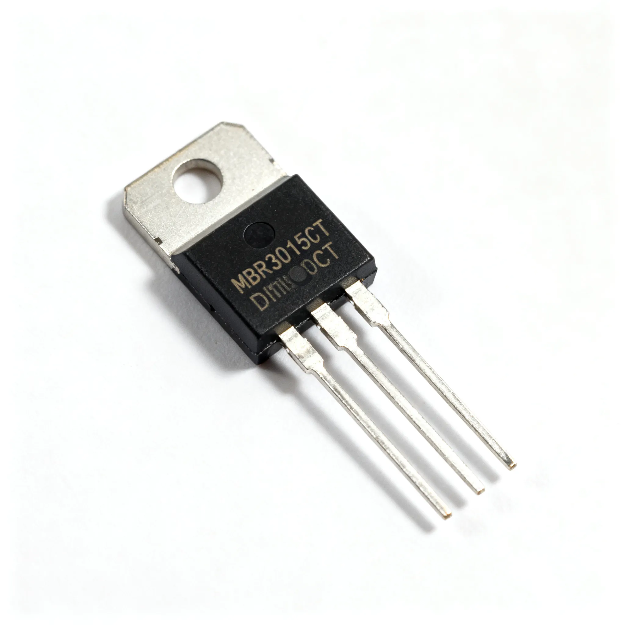
The MBR30150CT, a dual 30 A, 150 V Schottky barrier rectifier in a TO‑220AB package, is a workhorse in low‑voltage high‑frequency inverters, free‑wheeling circuits, and polarity‑protection front‑ends. Yet the part can introduce significant procurement friction: leading distributors do not hold regular stock. For example, Taiwan Semiconductor's version is not normally stocked at DigiKey — customer orders are passed straight to the manufacturer’s lead time. This means design teams that freeze the BOM without a clear allocation‑backed lead‑time commitment risk line‑down events later.
The situation is not a shortage, but it is an allocation‑sensitive supply landscape. Multiple manufacturers fabricate MBR30150CT‑branded parts, but not all are equally available, and datasheet parameters can diverge enough to affect thermal performance in your application. Engineers and buyers must therefore treat every bill-of‑materials line with the same discipline: verify, compare, and ask the right questions before committing to a production order.
Key takeaway: Do not assume that “MBR30150CT” is a fungible commodity. Confirm current allocation status and lead‑time via RFQ, and be ready to evaluate second‑source candidates with the structured comparison that follows.
Decoding MBR30150CT Specifications to Avoid Surprises
Before assessing supply risk, engineers need a crystal‑clear reading of the parameters that govern reliability and thermal design. The product is defined in multiple datasheets; we base the following reference table primarily on the GOOD‑ARK MBR30150CT specification and the aggregated data on Alldatasheet, which centralises offerings from several manufacturers.
| Parameter | Typical Value / Range | Unit / Notes |
|---|---|---|
| Maximum repetitive peak reverse voltage (VRRM) | 150 | V |
| Average forward current (IF(AV)) per leg @ Tc = 125 °C | 15 | A (dual common‑cathode, total 30 A) |
| Peak forward surge current (8.3 ms single half‑sine) | 275 | A |
| Forward voltage drop (VF) @ 15 A, Tj = 25 °C | 0.82 – 0.88 | V per leg |
| Forward voltage drop @ 15 A, Tj = 125 °C | 0.70 – 0.75 | V |
| Reverse leakage current (IR) @ 150 V, Tj = 25 °C | 0.1 – 0.5 | mA |
| Reverse leakage @ 150 V, Tj = 125 °C | 15 – 30 | mA |
| Junction‑to‑case thermal resistance (RθJC) per leg | ≤ 1.5 | °C/W |
| Operating junction temperature range | -55 to +150 | °C |
| Package | TO‑220AB | – |
These figures matter because very small differences in forward voltage directly alter conduction losses. At 15 A leg current, a shift from 0.82 V to 0.88 V adds almost 1 W of extra dissipation per device – enough to force a heat‑sink re‑spin. Moreover, the reverse leakage at elevated temperature (30 mA at 125 °C) can trigger thermal runaway if the layout does not provide adequate copper pour for cooling. Always check the worst‑case datasheet limits, not just typical values, and run a thermal simulation with the actual RθJC of the candidate part.
Alternative Manufacturers: Not All MBR30150CT Parts Are Equal
Three credible second‑source suppliers publish datasheets for the MBR30150CT footprint: GOOD‑ARK Electronics, Galaxy Microelectronics, and First Silicon. While all claim to meet the 30 A, 150 V headline, the detailed electrical data reveals subtle – yet critical – rating differences. The table below contrasts the two alternatives most likely to be quoted through independent distributors against the benchmark Taiwan Semiconductor part, which we treat as the reference despite its spotty stock.
| Comparison Metric | GOOD‑ARK MBR30150CT | Galaxy Micro MBR30150CT | Selection Criteria & Failure Boundary |
|---|---|---|---|
| Max. forward voltage @ 15 A, 25 °C | 0.88 V | 0.88 V | Verify measured VF at your actual operating current; any part exceeding 0.95 V at 25 °C suggests die‑attach issues. |
| Max. forward voltage @ 15 A, 125 °C | 0.75 V | 0.75 V | Lower is better for efficiency; confirm the same guard‑ring technology is used. |
| Typ. RθJC (per leg) | 1.2 °C/W | 1.4 °C/W | Higher RθJC forces a larger heat sink or derating; re‑simulate with 1.5 °C/W worst‑case. |
| Reverse leakage @ 150 V, 125 °C | 30 mA max. | 30 mA max. | Both are identical; still test actual leakage at your maximum expected ambient. |
| Operating junction temp. max. | +150 °C | +150 °C | De‑rate by at least 25 °C for reliability in continuous‑duty designs. |
Beyond numbers, the real differentiator is the manufacturer’s lifecycle support and the lead‑time profile you obtain when you request a quote. First Silicon also offers a viable variant, but its datasheet carries less detail on reverse‑recovery softness. In hard‑switching inverters, this can cause ringing and EMC trouble. Always ask the supplier for the latest PCN policy and request a sample with a full batch test report before qualifying a second source for production.
Supply Chain Questions to Ask Before You Finalize the BOM
Armed with parametric knowledge, procurement and design teams must systematically frame their RFQ to extract the information that prevents supply‑induced redesigns. The following table captures the minimum set of queries buyers should pose, who should own each, and what a red flag looks like.
| Risk Factor | Verification Action | Red Flag |
|---|---|---|
| Allocation‑backed lead time | Require a written commitment for EXW or FOB dates from the factory, not just a distributor estimate. | Vague “subject to change” clauses without a PCN process. |
| Lot traceability and date codes | Ask for date‑code distribution and a certification of origin; request a sample with batch‑specific test data. | Mixed date codes or reluctance to share assembly‑location details. |
| Thermal impedance in your layout | Measure RθJC and forward voltage on a representative PCB coupon under pulsed conditions. | Deviation > 5 % from datasheet typical suggests different die‑attach material. |
| Derating guidelines for elevated ambient | Request the manufacturer’s official derating curve; verify that it matches the actual SOA published in the latest datasheet. | Missing or “beta” charts that do not extend to 150 °C junction. |
| PCN / EOL communication | Confirm that the supplier will notify you at least 90 days before a process change or discontinuance. | No formal PCN agreement in the supply contract. |
| Reverse recovery behaviour | Perform a dynamic test at your switching frequency; ask the supplier for trr and soft‑recovery factor data. | Snappy recovery that generates voltage overshoot beyond 120 % of rated VRRM. |
Tip: Even an apparently identical MBR30150CT can exhibit different reverse recovery characteristics due to minor die‑attach and guard‑ring variations — a point underscored by cross‑comparing the GOOD‑ARK and Galaxy datasheets. Always test samples in the final circuit under worst‑case line and load conditions before releasing the BOM.
- Require a fixed lead‑time window with a max. delivery commit date per purchase order.
- Negotiate a consignment stock agreement with the distributor if the part is allocation‑sensitive.
- Validate the second‑source’s packaging: TO‑220AB outline tolerances can vary, affecting heat‑sink clamp force.
- Establish a parametric bridging test procedure to approve alternative suppliers without a full qualification.
MBR30150CT Sourcing and Specification FAQs
Senior engineers and procurement leads frequently raise these six pointed questions when the MBR30150CT comes under supply pressure.
Q: Can I substitute an MBR30200CT (200 V version) if the MBR30150CT can be allocation-sensitive — confirm availability via RFQ?
A: Often yes, because the MBR30200CT belongs to the same family with a higher breakdown voltage. Reverse leakage at your operating voltage will be lower, but the slightly higher forward voltage may increase conduction losses — check your thermal budget. Verify that the 200 V part is available from the same second‑source vendors and run a quick front‑of‑wave measurement to confirm that the efficiency margin remains within your design limits.
Q: What is the typical lead time for MBR30150CT parts from Asian fabs right now?
A: Lead times can vary — confirm via RFQ depending on the manufacturer. Orders through major distributors that do not hold stock (like DigiKey for Taiwan Semi) inherit the factory lead time. Always get a written commitment for EXW or FOB dates and ask about assembly‑site loading before placing a production order. Do not rely on generic “standard lead time” statements; request an allocation‑backed schedule tied to a purchase order.
Q: How do I validate a second‑source Schottky without a full qualification run?
A: Perform a limited “parametric bridging” test: measure forward voltage at rated current and hot junction, reverse leakage at maximum operating temperature, and thermal impedance under pulsed conditions. Compare the results directly with the primary source parts on the same test PCB. If the numbers match within ±5 %, the risk is low for most free‑wheeling applications. For hard‑switched circuits, add a reverse‑recovery waveform capture at full load to ensure softness is acceptable.
Q: Is there a risk of counterfeit MBR30150CTs?
A: The MBR30150CT is not considered high‑risk for sophisticated counterfeits, but remarking of lower‑grade dies does occur. Purchase only from authorized distributors or directly from the manufacturer, request lot‑specific test reports, and inspect laser marking and lead finish quality under magnification. Look for inconsistent pin‑1 chamfer edges or signs of re‑plating, which can signal remarking.
Q: Which parameters are most likely to drift when using a different manufacturer’s MBR30150CT?
A: Forward voltage drop (particularly at high current and temperature) and reverse leakage current at the upper end of the temperature range are the two most variable parameters. Subtle differences in die size and guard‑ring design also affect reverse recovery softness, which matters in hard‑switching inverters. Always characterise these across three samples per manufacturer to build a statistical picture.
Q: Should I consider an SiC Schottky alternative instead of hunting for MBR30150CT stock?
A: If switching speed or high‑temperature efficiency justifies the cost, a 150 V SiC Schottky in a TO‑220‑2 or TO‑247 package can outperform the MBR30150CT. However, SiC devices are typically single‑die, so a dual common‑cathode configuration may require a board layout change. Evaluate total cost and availability before changing the BOM. SiC rectifiers often show near‑zero reverse recovery charge, which can reduce EMI filter size but demand a gate‑drive snubber redesign.
References & Further Reading
- Digitally: MBR30150CT ‑ Taiwan Semiconductor Corporation, Diode Arrays
- GOOD‑ARK Electronics MBR30150CT Datasheet
- Alldatasheet – MBR30150CT aggregate listing
- Galaxy Microelectronics MBR30150CT Datasheet
- First Silicon MBR30150CT Datasheet
- IC-Online – RFQ & BOM upload platform
Supply volatility in discrete power rectifiers demands a proactive, specification‑driven approach. By treating the MBR30150CT as an allocation‑sensitive component rather than a guaranteed in‑stock commodity, you protect production schedules and thermal performance. Start your assessment with the parameter comparison above, question every supplier’s lead‑time promise, and qualify a second source before the first signs of inventory tightening appear.
To secure your MBR30150CT supply with allocation‑backed commitments, request a quote or upload your full BOM through IC-Online – mixed BOM, flexible MOQ, and direct access to verified manufacturers and distributors.