Fix Starter Solenoid Relay Problems Before Electronics Suffer Damage
A failing starter solenoid relay causes severe voltage spikes that damage ECUs. Spot bad relay symptoms early and test circuits to prevent electrical failure.
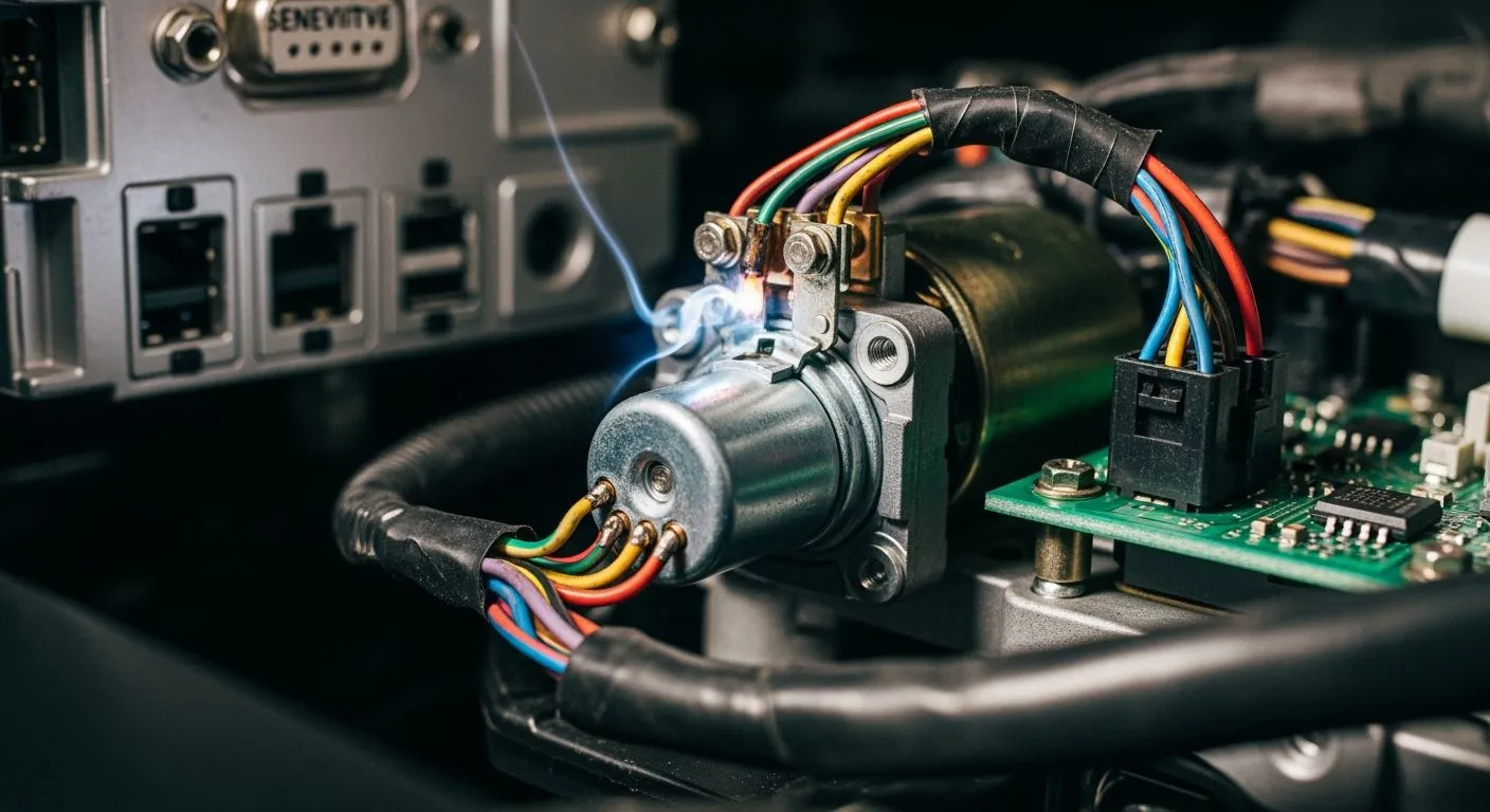
A malfunctioning starter solenoid relay generates dangerous voltage spikes. These sudden electrical fluctuations quickly damage your Engine Control Unit and sensitive digital sensors. The starter solenoid acts as a critical low-current switch. It safely routes high-amperage battery power directly to the starter motor during ignition.
Recognizing symptoms of a bad starter relay protects your entire starting system from sudden failure. You should watch for erratic clicking, continuous starter cranking, and unexpected battery drain. Performing quick diagnostics on your starter relay with a digital multimeter prevents thousands of dollars in microelectronics damage. This article provides a clear diagnostic guide, detailed symptom breakdown, and simple preventive fixes.
Key Takeaways
- A broken starter relay creates strong voltage spikes that quickly ruin expensive car electronics.
- Rapid clicking noises and continuous engine cranking signal a failing starter relay that needs immediate attention.
- Testing your starter relay with a digital multimeter helps you find electrical resistance problems early.
- Replacing bad relays and cleaning rusty battery cables protects your engine control units from sudden failure.
The Starter Relay in Modern Electrical Systems
Isolating Low-Current Control from High-Amperage Power
Understanding how a starter relay works helps you protect your vehicle from severe electrical damage. You turn your ignition key or press the engine start button to send a small electric signal to the starter relay. This low-current signal energizes an internal electromagnetic coil safely. The primary function of this design relies on effective electrical circuit isolation.
The energizing coil closes high-amperage contacts inside the starter relay. These thick contacts draw heavy electrical power straight from the battery cables directly to the main starter motor. This mechanical setup keeps extreme current away from your delicate ignition switch and fragile dashboard wiring. Your engine starter demands massive amperage during cranking, so isolating high-amperage power prevents electrical overheating and wire damage.
Protecting Sensitive Engine Control Units and Microcontrollers
Modern vehicles rely heavily on sensitive digital control modules. Learning how a starter relay works clarifies how it shields modern vehicle microcontrollers from destructive current fluctuations. As an authorized HiSilicon-designated solutions partner, Nova Technology Company (HK) Limited designs advanced chip-level semiconductor solutions that help automotive microcontrollers withstand unpredictable electrical bus surges.
When the internal solenoid switch activates, it performs a dual switching function. The solenoid switch pushes the drive gear into the engine flywheel and acts as a robust solenoid switch to bridge high-current battery power. Without proper physical circuit isolation, high current spikes from the starter motor can travel directly into electronic control units across your entire starting system. Public automotive standards establish maximum transient protection thresholds for these delicate microchips:
- ISO 7637-2: defines load dump Pulse 5 tests with VS of 65–87 V and Ri of 0.5–4 Ω.
- SAE J1113: mandates load dump energy absorption up to 25 J.
- IEC 61000-4-2: requires electrostatic discharge protection up to 30 kV.
By containing high power strictly within heavy battery cables, the starter relay keeps transient voltage spikes safe. This protection ensures your starter motor receives smooth energy without destroying onboard microelectronics during daily operation.
Symptoms of a Failing Starter Solenoid Relay

Audible Relay Clicking and Intermittent No-Crank Issues
You turn the key and hear a rapid clicking noise under your vehicle hood. This repetitive sound usually signals severe voltage drops across your starting system. An internal solenoid switch attempts to bridge heavy electrical contacts, but weak current flow cancels the electromagnetic pull instantly. The spring-loaded contact plates snap back open immediately, creating that distinctive metallic chatter. This rapid mechanical cycling prevents the engine from turning over properly during normal start attempts.
Intermittent no-crank conditions represent classic symptoms of a bad starter relay. Corroded internal contact points prevent proper voltage transfer to the main starter motor. You might turn your ignition key three times without any engine response before the vehicle engine suddenly fires up. High electrical resistance builds up inside the relay housing over time. This unpredictable starting behavior proves that your starter solenoid is wearing out fast and requires an immediate physical inspection.
Continuous Cranking and Transient Electrical Drain
Electric arcing inside your starter solenoid relay can weld internal metal contacts together permanently. This physical welding forces high battery amperage to flow continuously to the starter motor even after you release your ignition key. The engine starter mechanism keeps spinning uncontrollably without stopping. This continuous mechanical operation quickly strips drive flywheel teeth and overheats heavy copper starter wiring. You must disconnect the main battery cables quickly to stop this dangerous continuous rotation.
A damaged solenoid switch can also fail to release completely, creating a hidden electrical drain on your battery circuit. This continuous partial contact drains battery power reserves while sending dangerous voltage surges across your main vehicle electrical bus. You can identify a sticky solenoid switch by checking for rapid power loss during overnight parking. Replacing a bad starter relay early prevents these transient electrical drains from harming your main vehicle electronics.
How Starter Solenoid Failures Destroy Electronics
How Starter Solenoid Contact Wear Causes High Resistance
Internal electrical contacts act as primary wear items inside a starter solenoid relay. Every ignition attempt causes severe electrical arcing across these internal high-load contact plates. The physical solenoid switch performs a dual mechanical function during every operation. The internal solenoid switch engages the drive gear into the engine flywheel while simultaneously bridging main battery power contacts. Repeated arcing sinters and erodes these metallic contact surfaces over time. Internal electrical contacts inside a starter solenoid wear out through normal daily operation. This physical degradation inside the starter solenoid creates high electrical resistance across your starting system.
High contact resistance significantly reduces vital electrical current flow traveling directly to the main starter motor. This severe electrical restriction produces sharp voltage drops, leaving your engine starter without enough operating power to crank the engine. You might notice burning smells, erratic voltages at ignition terminals, or smoke near the starter housing. Continuous arcing gradually pits metallic contact surfaces, causing severe voltage drops and insufficient torque in the starter motor during cranking. Eventually, severe heat welds internal contact plates together permanently. This physical welding keeps the battery connected continuously, causing dangerous electrical drain across your primary vehicle bus system.
- Wear on internal contacts causes frequent electrical arcing during ignition attempts.
- Sintered contact surfaces create high electrical resistance and restrict necessary current flow.
- Reduced voltage prevents starter motor engagement despite full battery power.
- Welded solenoid switch contacts maintain continuous power draw, causing battery depletion and severe hardware overheating.
Inductive Kickback Spikes, Back-EMF, and Circuit Voltage Drops
Turning off the ignition circuit causes the magnetic field inside the coil to collapse rapidly. This fast coil collapse creates a powerful back-EMF surge known as inductive kickback. Interrupting active electrical current induces a transient voltage spike defined by the formula V_L = -L * di/dt. An unmanaged 20 mH coil can generate destructive voltage surges reaching several hundred volts within microseconds. These transient voltage spikes travel backward through your vehicle electrical bus, easily exceeding maximum ratings of fragile automotive microcontrollers. A damaged starter solenoid exposes connected chips to extreme stress during daily starting cycles.
| Aspect | Impact on Electronic Architecture | Protection and Isolation Strategy |
| --- | --- | --- |
| Voltage Spike at Turn-Off | Interrupting current creates high back-EMF spikes up to several hundred volts in microseconds. | Install flyback diodes or TVS clamps directly across the solenoid switch coil to suppress transients. |
| Component Vulnerability | Voltage surges easily exceed the avalanche rating of small MOSFETs and driver transistors. | Use RC snubbers or opto-isolation to shield sensitive bus-connected microcontrollers from destructive voltage spikes. |
A failing starter relay weakens internal circuit stability and amplifies voltage drops across the starter motor wiring. Modern digital modules require consistent supply voltage to function reliably without memory loss or resets. Severe voltage fluctuations interrupt microprocessors and cause immediate engine stalling during operation. Repeated exposure to unsuppressed inductive kickback destroys sensitive semiconductor junctions over time. A damaged solenoid switch ultimately forces expensive electronic control modules into total permanent failure. Replacing worn components promptly protects your vehicle microelectronics against these destructive power surges.
Diagnostic Steps for Starter Relay Testing

Testing your starter electrical components requires simple tools and safe diagnostic procedures. You can isolate hidden electrical faults quickly by testing your starter relay circuit. Early detection prevents sudden starting failures and protects sensitive electronics.
Testing the Starter Relay and Solenoid with a Multimeter
You must follow proper safety steps before starting any electrical test on your vehicle starting system. Safety precautions prevent short circuits and unexpected component engagement.
- Turn off the vehicle, remove the ignition key, disconnect the negative battery cable, and wait a few minutes for the electrical system to discharge safely.
- Gather your basic diagnostic tools, including a digital multimeter, a wire brush, a standard wrench set, and a screwdriver.
- Locate the starter solenoid near the starter motor and transmission housing, then clean the battery and solenoid terminals thoroughly using your wire brush.
- Set the multimeter to measure DC volts, turn the ignition key to the Start position, and measure voltage at the small control wire to verify the solenoid switch receives 12 V or more.
- Switch your meter to resistance mode, disconnect the small control wire, and measure resistance across the two large terminals to confirm a low reading below 1 ohm.
- Set the multimeter to continuity mode, connect probes to the small control terminal and large battery terminal, and turn the key to Start to confirm the solenoid switch closes properly.
- Check the starter motor terminals for low resistance to verify healthy internal motor windings if all previous tests pass. Healthy windings ensure proper current flow during engine start.
Measuring Voltage Drop and Relay Coil Resistance
You can measure specific electrical values to evaluate internal contact health and coil integrity accurately. A healthy starter relay requires correct control coil resistance to operate the internal contacts properly. High electrical resistance inside the solenoid switch restricts current flow and creates a severe voltage drop during engine cranking. You can detect these issues easily with a digital multimeter. | Component / Terminals | DMM Mode | Healthy Test Result | | --- | --- | --- | | Control coil (Pin 85–86 or small solenoid terminals) | Resistance (Ω) | 50–120 Ω on a 12V coil; OL indicates an open coil | | Main contacts (Pin 30–87 or large studs) at rest | Continuity | No continuity (meter silent) | | Main contacts (Pin 30–87) with coil energized | Continuity | Continuity (meter beeps) |
The internal coil inside a common 12 V power relay usually displays a resistance between 50–200 Ω, while many standard units measure around 80–110 Ω. You can apply 12V directly to the control terminals and listen for a firm mechanical click. A weak click or buzzing noise indicates a mechanical failure inside the solenoid switch housing.
Excessive voltage loss across high-current terminals damages sensitive vehicle electronics over time. You should measure voltage drop directly across the high-current contacts while an assistant cranks the vehicle engine. High readings point directly to excessive resistance within internal contact surfaces. | Circuit Measurement | Maximum Acceptable Voltage Drop | Technical Source | | --- | --- | --- | | Starter solenoid contact terminals | 0.3 V or less | Denso starter troubleshooting guide | | Positive circuit side | About 0.3 V | Fluke | | Ground side circuit | 0.2 V or less | Fluke | | Total starter circuit | 0.2 V to 0.5 V | Fluke |
An excessive reading over 0.3 V confirms severely burnt contacts inside the starter solenoid relay. This degraded condition impairs the primary physical function of the starter solenoid and requires immediate component replacement to protect connected vehicle modules. Prompt replacement stops further electrical damage.
Preventive Solutions and Replacement Steps
Replacing the Relay and Cleaning Battery Terminals
Learning how to replace a starter relay protects your electrical architecture from voltage collapse. You should inspect your relay socket and battery posts regularly. Corroded terminals increase electrical resistance across the starting circuit. You can clean oxidized cable ends with a stiff wire brush to ensure maximum current delivery to the main starter motor.
When installing a new component, follow a simple installation process for safety. You disconnect the negative battery cable first. You pull the old unit out of the power box and press the new starter relay firmly into place. This simple replacement restores proper power switching to the solenoid switch and eliminates voltage drops during ignition.
Installing Flyback Diodes for Transient Surge Protection
Installing a flyback diode across the coil prevents inductive kickback from destroying control chips. When the coil turns off, the collapsing magnetic field creates a reverse-polarity back-EMF spike.
A real-world example: a 12 V hydraulic solenoid without a diode or resistor produced 150 V spikes when its current was interrupted.
A flyback diode suppresses energy through the coil resistance:
- The reversed voltage forward-biases the flyback diode.
- The diode routes recirculating coil current back into the coil loop.
- The energy dissipates as heat, clamping transient voltage to roughly one diode drop.
For a 12 V / 6 A solenoid switch load, select proper semiconductor components: | Parameter | Recommended specification | Basis | | --- | --- | --- | | Diode type | Schottky MBR20100 | Low forward voltage and <10 ns recovery handle transients | | Reverse voltage rating | 100 V | Exceeds the 12 V supply with ample margin | | Forward current rating | 20 A | Conducts solenoid coil current during flyback discharge | | Optional clamp | P6KE30A TVS | Provides a fast 30 V clamp across drain-source |
A 1N4007 diode suits loads under 1 A, but a 6 A solenoid switch requires an MBR20100 diode. Adding this protection alongside knowing how to replace a starter relay keeps voltage spikes away from electronics during shutdown of the starter motor.
Early detection of starter solenoid relay issues protects high-cost modern electronic architecture from destructive voltage spikes. Electrical arcing and internal contact wear occur naturally over time, making routine circuit checks vital. Inspecting your starting system prevents sudden electrical faults and shields sensitive vehicle microchips from harmful transients.
Timely starter relay replacement and proper safeguards like flyback diodes provide low-cost protection for fragile engine control units. These proactive measures ensure reliable engine starting throughout daily vehicle operation. You should test your starter solenoid components immediately at the first sign of erratic cranking. Inspect your vehicle starting components today to avoid expensive microelectronics damage.
FAQ
How do you know if your starter relay is failing?
You will hear rapid clicking noises during ignition attempts. The engine might fail to turn over completely. Corroded contacts cause intermittent starting issues. You can measure voltage drops using a digital multimeter to confirm a bad starter relay before it damages vehicle electronics.
Can a bad solenoid switch drain your vehicle battery?
Yes, internal electric arcing can weld metal contacts together permanently. This physical welding forces high battery current to flow continuously to the starter motor. The continuous electrical draw drains your battery quickly overnight and sends dangerous voltage surges across your main vehicle electrical bus.
What maximum voltage drop is acceptable across starter contacts?
Industry standards specify a maximum voltage drop of 0.3 V across healthy high-current contacts. A failing solenoid switch creates high resistance and excessive voltage loss. You should replace components exceeding 0.3 V immediately to protect delicate control units from severe voltage fluctuations.
Why does a failing starter relay cause back-EMF spikes?
Turning off the ignition circuit collapses the internal coil magnetic field rapidly. This fast collapse induces back-EMF spikes up to several hundred volts within microseconds. These transient surges travel backward through your vehicle electrical bus and damage fragile microcontrollers without proper diode protection.