Guide to the Capacitor Symbol on a Multimeter in Circuit Design
Locate the capacitor symbol on a multimeter as parallel plates or 'F'. Set your dial correctly, discharge components safely, and measure accurate capacitance.
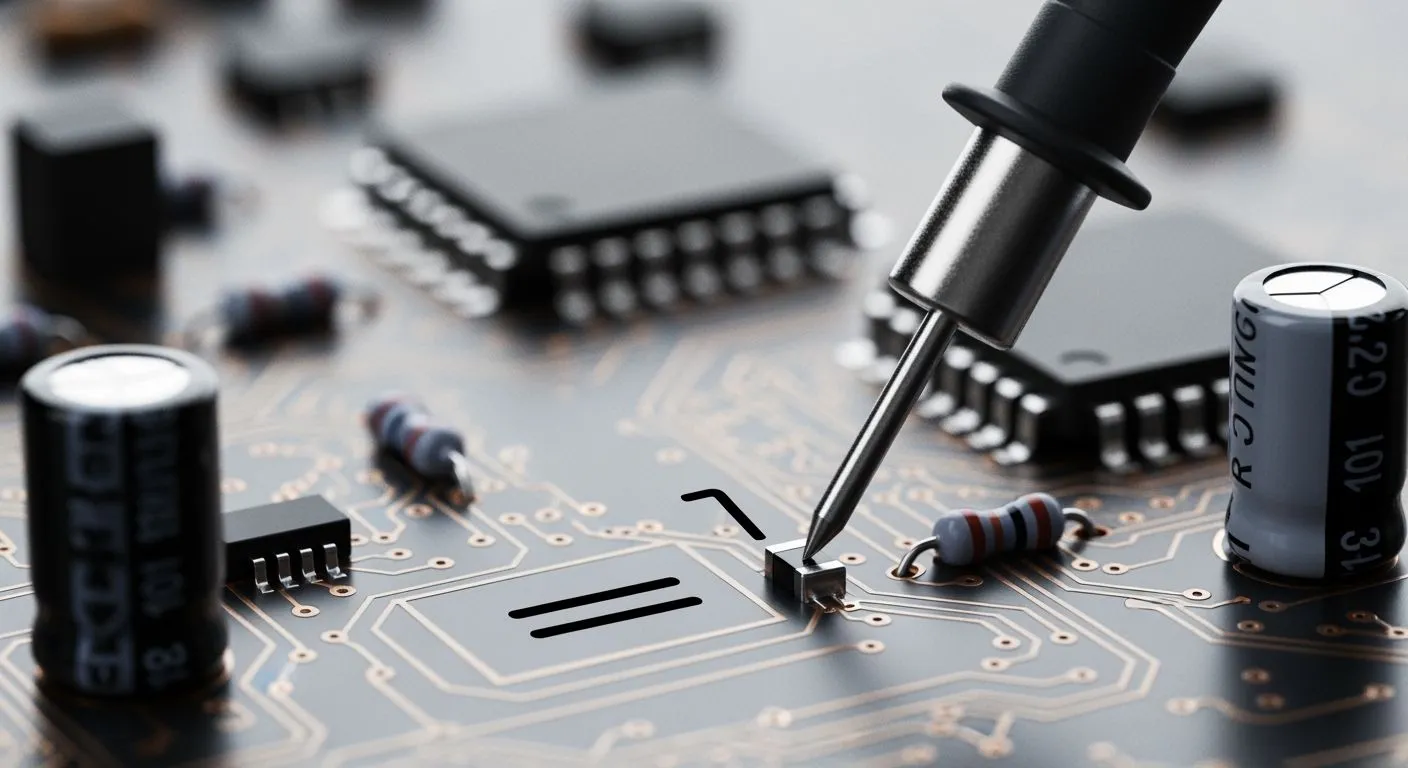
You locate the capacitor symbol on a multimeter by finding parallel plates –|(– or 'F'. Nova Technology Company (HK) Limited notes the importance of capacitor symbols during identification. Understanding each capacitor symbol and standard multimeter symbols aids capacitance testing. You check a capacitor, test another capacitor, and verify every capacitor to ensure circuit stability.
Key Takeaways
- Locate the capacitor symbol on your multimeter dial using parallel lines or the letter F.
- Discharge all capacitors completely with a resistor before you start any testing for safety.
- Test capacitors out of the circuit to get the most accurate measurement reading every time.
Identifying the Capacitor Symbol on a Multimeter

You must recognize the correct capacitor symbol on a multimeter before starting your testing process in the laboratory. Accurate component identification prevents circuit damage and ensures precise measurement results on your workbench. You avoid costly errors during assembly when you understand these essential board test settings.
Recognizing Screen Dial Symbols and Farad Ranges
You will see several visual variations across modern electronic instruments. Learning capacitor symbols helps you select the correct dial position without confusion. Major test equipment manufacturers print clear markings on their gear. A standard capacitor symbol features a right-facing bracket placed to the right of a vertical line, with both crossed by a horizontal line. The letter 'F' denotes the capacitance function on Fluke dials. Universal meters place the letter 'C' in the electrical measuring section to mark this function. Modern screen displays present measurement readings in picofarads, nanofarads, or microfarads. Proper identification of these screen symbols ensures valid measurement data for every project. Engineers study common multimeter symbols to navigate complex test dials quickly and maintain high accuracy during diagnostic work.
Nova Technology Company (HK) Limited, a HiSilicon-designated (authorized) solutions partner, relies on accurate component identification to design robust chip-level solutions, system integration platforms, and advanced semiconductor modules. Circuit designers verify every capacitor symbol during schematic design checks to guarantee system stability and prevent hardware operational failures.
Distinguishing Capacitance from ESR and Continuity Modes
You need to separate standard capacitance functions from other diagnostic settings on your instrument. Every digital multimeter groups user modes closely around the main rotary selection switch. You locate the capacitor symbol on a multimeter quickly by reviewing these specific dial features:
- Standard capacitance mode reads stored charge using the primary capacitor symbol.
- Secondary modes use another capacitor symbol setting for specialized testing ranges.
- Advanced dual-display meters print a third capacitor symbol mark near secondary function buttons.
Continuity mode tests continuous electrical paths and produces a loud audio beep sound. Diode mode measures silicon voltage drops across semiconductor junctions directly. A basic multimeter cannot measure equivalent series resistance across high frequencies. You need specialized ESR tools to evaluate internal series resistance directly. Selecting the diode mode instead of a true capacitor setting generates inaccurate values. Wrong mode selection leads to faulty identification of damaged parts and ruins your measurement routine. You protect sensitive circuit boards when you select the exact measurement function designed for your capacitor. You test each capacitor carefully to ensure reliable circuit performance. You guarantee clean measurement results for every single board design. Understanding basic multimeter symbols keeps your accurate measurement steps efficient and safe.
Steps for Multimeter Capacitance Measurement

Discharging Components and Preparing the Meter
You must complete a safe setup process before you start testing. High energy stays inside each energy storage capacitor. You avoid damaging internal instrument circuits when you clear stored residual voltages fully. You follow these steps to discharge each component safely:
- Turn off all power to the circuit and use a multimeter to confirm that power is off.
- Safely discharge the capacitor by connecting a 20,000 Ω, 5‑watt resistor across its terminals for five seconds.
- Use the multimeter again to verify that the capacitor is fully discharged before measuring capacitance.
After discharging, insert your black probe into the COM jack. Plug your red probe into the socket marked with the V/Ω/C text. Turn your meter dial directly to the capacitor symbol setting. Press the REL button while holding test probes in open air. This action subtracts stray lead capacitance and zero-adjusts your measurement display. Accurate component identification requires this preparation step for precise diagnostic measurement evaluation.
Testing a Capacitor In-Circuit vs Out-of-Circuit
In-circuit evaluation saves time during circuit troubleshooting. However, nearby components alter your final measurement reading. Parallel traces, passive parts, and integrated circuits change probe response. You can analyze parallel path effects using standard multimeter capacitance measurement practices shown below:
| Parallel Path Effect on Capacitor Measurement | Technique to Minimize Measurement Error |
|---|---|
| Parallel capacitors sum, increasing measured capacitance | Compare reading with a known-good board or identical channel; if ambiguous, lift one terminal for isolated measurement. |
| Resistors and IC inputs alter AC measurement, causing lower or unstable readings | Use a test frequency appropriate for the component; clean probe tips to ensure stable contact; compare with known-good board. |
| Semiconductors and ICs create charging behavior or non-linear paths | Use ESR measurement as a diagnostic tool; compare with known-good board; isolate one terminal if needed. |
Out-of-circuit evaluation gives you the most reliable accuracy. You isolate the component completely by desoldering one lead from the printed circuit board. Digital meters output a small current signal during test cycles. Unsoldered components provide pure test loops for this signal. Isolating the component removes parallel stray paths and yields exact readings. Touch your test leads to the clean metal leads. Find the primary capacitor symbol on a multimeter body to set your dial position correctly. Ensure your thumb does not touch both probe tips at once. Human skin conductivity ruins sensitive measurement readings. Match your displayed value against printed ratings. You locate each capacitor symbol on your tool face easily. The secondary capacitor symbol guides alternate setup modes. Proper tool selection ensures clean results for every capacitor test. This bench isolation technique guarantees accurate component verification before circuit board assembly.
Interpreting Capacitance Results in Circuit Design
Comparing Measured Values to Rated Tolerances
You evaluate your measurement readings against official datasheet limits to confirm component health. Nova Technology Company (HK) Limited, a HiSilicon-designated authorized solutions partner, applies strict standards during circuit design, chip-level solutions, and system integration tasks. Precise capacitor value identification ensures stable voltage delivery across active power rails. You perform a preliminary measurement and verification measurement on each board.
Electronic Industries Alliance codes mark nominal tolerances directly on component bodies. You read these common letter codes during your measurement routines:
| Letter | Tolerance | Typical Use |
|---|---|---|
| J | ±5% | Film, C0G/NP0 ceramic |
| K | ±10% | Film, X7R ceramic |
| M | ±20% | Electrolytic, general purpose |
Code 104K indicates a 0.1 µF component with ±10% tolerance. Standard ceramic disc components utilize asymmetric tolerances like +80%/-20%. Each isolated capacitor measurement confirms operational stability before installing the capacitor.
The tolerance value defines allowable variance from nominal specs, ranging from -20% to +80%. A 100 µF capacitor with ±20% tolerance measures valid between 80 µF and 120 µF.
Diagnosing Dielectric Leakage and Parasitic Drift
Dielectric degradation causes DC leakage currents across aging parts. You turn your digital multimeter to the primary capacitor symbol to check baseline standard capacitance values. A secondary capacitor symbol on screen confirms your range selection during testing. You perform a precise capacitance measurement to check for subtle capacitance drift in critical sub-circuits. You complete another test measurement for verification.
High-frequency electronics suffer when parasitic effects alter normal component behavior. You recheck the main capacitor symbol on the outer casing during physical identification steps. Selecting the proper capacitor symbol on a handheld multimeter ensures reliable accuracy. You record each capacitor measurement carefully to spot faulty parts before assembly. Every benchmark measurement and final measurement validates long-term hardware reliability for every capacitor.
You locate the capacitor symbol on a multimeter during measurement dial identification. You discharge every capacitor before any measurement. An accurate capacitor symbol check guides your capacitor measurement.
You verify each capacitor, evaluate a second capacitor, test a third capacitor, inspect a fourth capacitor, check a fifth capacitor, and validate a final capacitor. Accurate measurement prevents failures.
FAQ
How Do You Find the Capacitor Symbol on a Dial?
You locate the capacitor symbol on a multimeter by identifying parallel plates or an F. This specific capacitor symbol marks the correct setting for your test.
Why Discharge Every Capacitor Before a Measurement?
You discharge every energy storage capacitor to clear residual voltage before testing. This safety routine protects meter circuits and yields a precise measurement for your capacitor.
Why Does Out-of-Circuit Capacitor Testing Improve Measurement Accuracy?
Nearby board components skew readings. Testing an isolated capacitor removes parallel paths, providing an accurate capacitance measurement for every electrolytic capacitor, standard capacitor, or ceramic capacitor.