Why Your CAN Network Has Low Resistance and How to Fix It
A controller area network experiences low resistance from three main issues. These are excess termination resistor
A controller area network experiences low resistance from three main issues. These are excess termination resistors, a direct short between CAN_H and CAN_L wires, or a faulty network node. The CAN protocol is a digital networking protocol. It relies on specific electrical characteristics for a stable CAN system. A healthy CAN bus measures approximately 60 Ohms of resistance. Low CAN network low resistance corrupts the CAN signal and degrades signal quality. The bus impedance must remain stable.
Note: Any significant deviation from the 60-Ohm resistance indicates a problem. This low impedance value disrupts the CAN protocol's differential signal, causing data errors and potential system failure. This guide helps diagnose and fix the root cause.
Key Takeaways
- A healthy CAN network should have about 60 Ohms of resistance. If the resistance is too low, it can stop the network from working right.
- Low resistance can happen if there are too many termination resistors, if the CAN_H and CAN_L wires are touching, or if a network part is broken.
- You can check the network's resistance with a multimeter. Always turn off the power and disconnect the battery first.
- To fix low resistance, remove extra resistors, find and repair any shorted wires, or find and replace a broken network part.
- Fixing these problems helps the CAN network send clear messages and keeps your vehicle's electronics working well.
Diagnosing a CAN Network Low Resistance Problem
A technician can diagnose a can network low resistance issue by observing symptoms and measuring the bus. Correct diagnosis is the first step toward restoring a stable can system. This process involves recognizing operational faults and taking precise electrical measurements.
Common Symptoms of Low Resistance
Physical symptoms often provide the first clues to a network problem. A faulty CAN bus can cause unpredictable behavior in a vehicle's electronics. Technicians may observe several common issues:
- Power-door locks or windows fail to operate correctly.
- Turn signals flash abnormally or stay illuminated.
- The body-control module (BCM) warning lamp activates.
- Interior lighting dims or fails intermittently.
- The system generates excessive error frames, indicating frequent communication problems.
These symptoms suggest the underlying electronics are not receiving clear commands through the CAN bus.
Impact on CANbus Communications
Low resistance directly harms canbus communications. The incorrect impedance degrades signal quality and weakens the anti-interference performance of the protocol. This degradation causes signal reflections, where the electrical signal bounces back along the wire. The reflected signal interferes with new data, leading to corrupted messages and data loss. As a result, the communication becomes unreliable.
This instability often triggers diagnostic trouble codes (DTCs). A system might log general communication faults like J1939 SPN 625 or specific module failures. When errors become too frequent, a node may enter a "bus off" state, ceasing all can communications to protect the network.
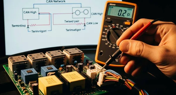
How to Measure Network Resistance
Measuring the network's resistance is the most direct way to confirm a fault. This measurement provides a clear health status of the CAN bus physical layer.
Important: Before measuring, a technician must power down the entire network. Disconnecting the battery is essential. Measuring a live circuit can damage the multimeter and the vehicle's electronics, and it will provide an inaccurate reading.
With the system powered off, a technician can set a multimeter to the Ohms (Ohms) setting. They should then place the probes on the CAN_H and CAN_L pins of the network's diagnostic connector. The reading reveals the state of the bus impedance.
| Multimeter Reading | Network Status | Likely Cause |
|---|---|---|
| ~60 Ohms | Healthy | Two 120 Ohms termination resistors are present. |
| ~40 Ohms | Faulty | Three 120 Ohms termination resistors are likely on the bus. |
| ~30 Ohms | Faulty | Four or more termination resistors are present. |
| Near 0 Ohms | Faulty | A direct short exists between CAN_H and CAN_L wires. |
Interpreting these values correctly is crucial for effective troubleshooting. For complex diagnostics involving the can protocol, consulting with an expert can be beneficial. For instance, Nova Technology Company (HK) Limited, a HiSilicon-designated (authorized) solutions partner, provides specialized expertise in resolving such canbus communication system issues.
Correcting CAN Bus Termination Faults
A multimeter reading below 60 Ohms often points to an incorrect number of termination resistors. Correcting this fault requires understanding the termination rule and methodically auditing the network. Proper termination is essential for a stable can system.
The 120-Ohm Resistor Rule
The CAN protocol specifies that a network must have exactly two 120-Ohm termination resistors. Engineers chose this value because it matches the characteristic impedance of the twisted-pair cable used for the can bus. This impedance matching is critical for maintaining signal integrity. When the resistor value matches the cable's impedance, it absorbs the signal at the end of the line, preventing reflections that corrupt data.
- The characteristic impedance of a cable is not arbitrary. It is an inherent electrical property.
- Technicians can find this value by connecting a cable to a signal generator and an adjustable resistor.
- They adjust the resistor until the signal on an oscilloscope is clean, without ringing or distortion.
- For typical CAN cables, this ideal resistance value is 120 Ohms.
How Extra Resistors Lower Resistance
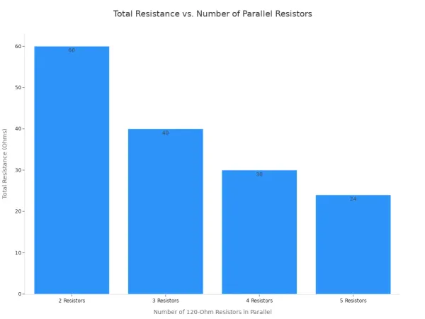
When technicians add more than two termination resistors to the bus, they create additional parallel paths for the electrical current to flow. This lowers the total network resistance. The total resistance in a parallel circuit is calculated with a specific formula.
The formula for total resistance ($R_{\text{total}}$) is:
1/R_total = 1/R1 + 1/R2 + 1/R3 + ...
A healthy CAN network with two 120-Ohm resistors has a total resistance of 60 Ohms. Adding a third 120-Ohm resistor drops the total impedance to 40 Ohms. Adding a fourth lowers it further to 30 Ohms. This drop in impedance overloads the transceivers and degrades the signal.
Auditing and Removing Extra Terminators
To fix a termination fault, a technician must locate and remove any extra resistors. This process requires a careful audit of the network. Some termination resistors are simple components plugged into a harness. Others are integrated directly inside an Electronic Control Unit (ECU). For example, one resistor might be in the Engine Control Module (ECM) and the second in the Body Control Module (BCM). Technicians should consult the vehicle or machine's wiring diagrams to identify the intended locations of the two primary termination points. They can then inspect the can network for any additional, non-standard resistors that may have been added during previous repairs or modifications.
Finding and Fixing a Wiring Short

A multimeter reading near zero Ohms is a clear sign of a direct short circuit. This fault requires a physical inspection of the wiring harness to locate and repair the damage. Finding the source of the short restores the correct bus impedance and allows the network to function properly.
What a Near-Zero Ohm Reading Indicates
A resistance reading near 0 Ohms indicates that the CAN_H and CAN_L wires are physically touching. This creates an unintended, low-resistance path for the electrical current. The proper differential voltage between the two lines collapses. As a result, the network's transceivers cannot distinguish between dominant (0) and recessive (1) bits. This complete loss of signal integrity halts all communication on the bus, effectively shutting down the network. The low impedance overloads the automotive electronics, which can lead to further damage if not corrected.
Common Causes of CAN Wiring Shorts
Wiring shorts in an automobile often result from physical damage. The constant vibration, heat, and movement in a vehicle can compromise the wiring harness over time. Common causes include:
- Chafed Insulation: Wires rubbing against sharp metal edges or brackets can wear away the protective insulation.
- Pinched Wires: Cables routed through door jambs, engine bays, or near moving parts can become pinched or crushed.
- Connector Damage: Bent or touching pins inside a connector can create a short. Moisture intrusion can also cause corrosion that bridges the terminals.
- Improper Repairs: Previous repairs using incorrect splicing methods or poor routing can introduce new failure points in the automotive electronics.
A Guide to Inspecting Wires and Connectors
A methodical visual inspection is the most effective way to find a wiring short. A technician should trace the can bus wiring through the vehicle, paying close attention to high-risk areas.
Safety First: Before starting, a technician must ensure the vehicle is off and the battery is disconnected to prevent electrical shock or damage to the electronics.
- Use a bright flashlight to trace the can harness, looking for abrasions where it might rub against engine components or brackets.
- Check areas where the harness flexes, such as near the engine or suspension, for signs of internal wire breakage.
- Inspect the plastic conduit for brittleness or cracks, which often indicate heat damage and may hide melted wires inside.
- Look for swollen sections of the harness, a sign of internal corrosion from moisture, especially near wheel wells.
- Disconnect connectors and examine the metal pins for corrosion, which appears as a green or white chalky substance. Ensure no pins are bent or touching.
If a visual check does not reveal the short, a technician can use a multimeter's continuity setting. By disconnecting both ends of a can segment and testing for continuity between the CAN_H and CAN_L wires, a beep will confirm a short. This helps isolate the faulty section of the harness for a more focused repair.
Isolating a Defective Network Node
Sometimes the wiring is perfect, but the resistance is still low. This situation often points to a faulty network node. A defective transceiver inside an Electronic Control Unit (ECU) can mimic a wiring short, disrupting the entire system.
How a Failed Transceiver Causes Issues
A CAN transceiver is a small chip inside each node. It converts digital data from the node's processor into the electrical signal sent over the bus. It also receives the signal and converts it back to digital data. These transceivers can fail due to electrical stress or manufacturing defects.
A common failure mode is an internal short. The internal components of the transceiver can break down, creating a direct connection between the CAN_H and CAN_L pins. This internal short has the same effect as touching the wires together. It causes the network impedance to drop, which corrupts the differential signal and stops all communication. The automotive electronics in that node become the source of the network failure.
The "Disconnect and Re-Measure" Method
The most reliable way to find a faulty node is through a process of elimination. This methodical approach helps a technician pinpoint the exact source of the problem without guesswork. The goal is to isolate the component causing the low resistance reading.
- Confirm the Fault: With the power off, measure the resistance across CAN_H and CAN_L at the diagnostic port. Confirm the reading is low (e.g., ~40 Ohms, ~30 Ohms, or near 0 Ohms).
- Disconnect a Node: Consult a wiring diagram to identify the nodes on the can network. Start at one end of the bus and disconnect the first ECU.
- Re-Measure: Measure the resistance again. If the reading returns to a healthy ~60 Ohms, the node just disconnected is the faulty one.
- Repeat if Necessary: If the resistance remains low, reconnect the node and move to the next one in the circuit. Repeat the disconnect and re-measure process until the faulty node is found.
Isolating a Faulty CAN Node
Once the faulty node is identified, the repair is straightforward: replace the defective unit. In complex automotive systems with intermittent faults, a multimeter alone may not be enough. Advanced tools can provide deeper insight into the can protocol and network behavior. These tools help confirm that a specific node is sending a bad signal or creating errors.
- Oscilloscope: This tool allows a technician to visually inspect the shape of the electrical signal on the bus, identifying noise or distortion caused by a failing component.
- CAN Analyzer: An analyzer monitors all traffic on the network. It can detect error frames, identify which node is creating them, and measure the overall bus load.
Using these tools helps verify that a node's electronics are failing and disrupting the network.
Technicians can resolve a can network low resistance issue by following a clear diagnostic path. A successful repair depends on methodically addressing one of three root causes.
- Ensuring the can bus has exactly two 120-Ohm resistor terminators.
- Inspecting the wiring harness for physical shorts between can wires.
- Isolating a faulty node by disconnecting modules sequentially.
Pro Tip: A quick multimeter measurement to verify the ~60 Ohm resistance is the most effective first step. Maintaining updated network documentation helps technicians troubleshoot any can system faster, minimizing downtime for the entire protocol and its connected impedance.
FAQ
Why is 60 Ohms the correct CAN bus resistance?
A healthy CAN bus uses two 120-Ohm resistors in parallel. This design creates a total resistance of 60 Ohms. The value matches the cable's impedance, which prevents signal reflections. This ensures all electronic control units receive clear communication signals on the network.
Can a technician measure resistance with the power on?
No. A technician must always disconnect the battery and power down the system first. Measuring a live circuit is dangerous. It can damage the multimeter and the vehicle's electronics. It also provides an inaccurate reading, which makes a correct diagnosis impossible.
What does a high resistance reading mean?
A high resistance reading, typically 120 Ohms, indicates a problem. This fault usually means one of the two termination resistors is missing or there is a break in one of the CAN wires. This open circuit also causes communication errors and must be repaired.
Is a CAN analyzer always needed for diagnosis?
A multimeter is sufficient for most common resistance faults. However, for complex or intermittent issues, a CAN analyzer is a powerful tool.
An analyzer helps a technician:
- Identify specific nodes causing errors.
- Detect high rates of error frames.
- Confirm a diagnosis before replacing an expensive ECU.