Mastering The Micro Farad Symbol For Your Projects
The micro farad symbol appears on nearly every circuit board, typically as μF, uF, or MFD. The official microfarad
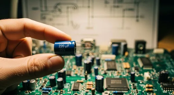
The micro farad symbol appears on nearly every circuit board, typically as μF, uF, or MFD. The official microfarad symbol, μ, originates from the Greek word small (small) and signifies one-millionth. While the Farad (F) is the base unit of capacitance, it is impractically large for most electronics applications. The microfarad is therefore the standard capacitance value for a capacitor. This guide helps you read any microfarad capacitor and understand its function. Mastering this microfarad symbol is key to understanding a capacitor's function in various applications and building with confidence.
Key Takeaways
- The microfarad symbol, like
μF,uF, orMFD, shows a capacitor's value. This symbol is important for all electronic projects. - Larger capacitors show their value directly. Smaller capacitors use a three-digit code. You must convert this code to find the microfarad value.
- Capacitors have many uses. They smooth power, manage signals, and create timing in circuits. The microfarad value changes how they work.
- Always check a capacitor's voltage rating. Use a capacitor with the same or higher voltage. This prevents damage and ensures safety.
- Understanding the microfarad symbol helps you choose the right capacitor. This skill is key for building and fixing electronics.
Decoding The Micro Farad Symbol

A capacitor's markings are a roadmap to its specifications. Understanding these markings is essential for choosing the right component. Manufacturers use several methods to label a capacitor, from plain text on larger units to compact codes on smaller ones.
Reading Capacitor Markings
Larger capacitors, like electrolytic and some film types, often have their specifications printed directly on their bodies. This makes them easy to identify. You will commonly see the capacitance value written out.
μF: This is the official microfarad symbol. For example,470μFmeans 470 microfarads.uF: Keyboards lack the Greek 'mu' symbol (μ), souFis a widely accepted substitute for microfarad.MFDorMF: These are older abbreviations for microfarad. You might find them on vintage equipment or schematics.
Alongside the capacitance, you will find other critical specifications. Manufacturers indicate voltage ratings with a number followed by 'V', such as 25V or 50V. This number represents the maximum voltage the microfarad capacitor can safely handle. It is crucial not to exceed this voltage. These direct markings provide the essential specifications needed for most applications.
Converting Numeric Capacitor Codes
Smaller ceramic, tantalum, and film capacitors lack the space for printed text. Instead, they use a standardized numeric code. The most common system is a three-digit code based on American EIA standards. This code tells you the capacitance in picofarads (pF), which you can then convert to microfarads.
Here is the step-by-step process to read the code on a microfarad capacitor:
- Identify the significant digits. The first two numbers of the code are the significant digits of the capacitance value.
- Find the multiplier. The third digit tells you how many zeros to add to the first two digits. It is a multiplier of 10 raised to the power of that third digit.
- Calculate the total capacitance in Picofarads (pF). Multiply the significant digits by the multiplier. For a capacitor marked
104, the calculation is10x 10⁴, which equals 100,000 pF. - Convert to Microfarads (μF). Since one microfarad equals one million picofarads, you divide the pF value by 1,000,000. So, 100,000 pF / 1,000,000 = 0.1 μF.
This simple function allows you to determine the value of most small capacitors.
Quick Tip: Tolerance Codes Often, a letter follows the three-digit code. This letter indicates the tolerance, or the acceptable range of deviation from the stated capacitance. This is another one of the component's key specifications.
- J = ±5%
- K = ±10%
- M = ±20% A microfarad capacitor marked
104Khas a capacitance of 0.1 μF with a ±10% tolerance. Its actual capacitance is between 0.09 μF and 0.11 μF.
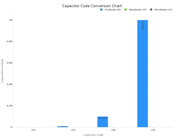
For convenience, here is a chart for converting common codes. Understanding this chart helps you quickly identify the microfarad symbol value in your projects.
| Capacitor Code | Picofarads (pF) | Nanofarads (nF) | Microfarads (μF) |
|---|---|---|---|
| 102 | 1,000 pF | 1 nF | 0.001 μF |
| 103 | 10,000 pF | 10 nF | 0.01 μF |
| 104 | 100,000 pF | 100 nF | 0.1 μF |
| 105 | 1,000,000 pF | 1,000 nF | 1.0 μF |
While the three-digit system is prevalent, international standards like IEC 60062 define other marking schemes. You might see codes where a letter (p, n, u) acts as a decimal point. For precision capacitors, a special two-character code defined by standards like ANSI/EIA-198 may be used. Always check the component's datasheet if you are unsure about its specifications, as this document contains the complete details of its function and limitations. Knowing these different ways to read the micro farad symbol ensures you can identify any microfarad capacitor you encounter.
Common Microfarad Capacitor Applications
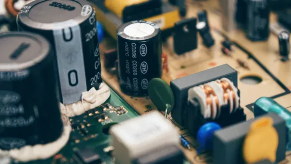
Once you can identify a capacitor's value, the next step is understanding its role in a circuit. The microfarad value directly influences a capacitor's behavior and its suitability for various electrical applications. A capacitor has a specific function based on its capacitance. Let's explore three of the most common applications for a microfarad capacitor.
Power Supply Filtering
One of the most critical applications for a capacitor is in power supply circuits. Most electronic devices require a smooth, stable direct current (DC) voltage to operate correctly. However, the process of converting alternating current (AC) from a wall outlet to DC often leaves behind small voltage fluctuations known as "ripple." This is where power supply smoothing comes in.
Large electrolytic capacitors, often with values like 470μF or higher, are used for this smoothing function. They act like tiny, rechargeable electrical batteries.
- The capacitor stores electrical energy when the voltage is at its peak.
- It releases that energy when the voltage begins to drop.
This action effectively "fills in the gaps" in the rippling voltage, resulting in a much smoother DC output. The amount of capacitance needed depends on the load current and the acceptable ripple. A larger capacitance provides better smoothing.
Calculating Your Smoothing Capacitor You can determine the required capacitance for power supply smoothing with a formula:
C = I / (2 x f x Vpp).
Cis the capacitance in Farads.Iis the load current in Amps.fis the input AC frequency in Hertz (e.g., 50Hz or 60Hz).Vppis the acceptable peak-to-peak ripple voltage. For a load current of 2 Amps, a frequency of 50 Hz, and a desired ripple voltage of 1 Volt, you would need2 / (2 * 50 * 1)= 0.02 Farads, or a massive 20,000 microfarad capacitor. This shows why proper component selection is vital for electrical applications. Using a microfarad capacitor with too low a capacitance for power supply smoothing will result in insufficient smoothing and a higher ripple voltage, which can cause poor performance or damage to sensitive electrical components.
Signal Coupling And Decoupling
Capacitors are essential for managing signals in audio, radio, and digital logic applications. Their ability to block DC voltage while allowing AC signals to pass makes them perfect for isolating different parts of a circuit. These applications often use a smaller microfarad capacitor.
Coupling capacitors connect two different stages of an electrical circuit, such as in an audio amplifier. For example, a 10μF capacitor can be used to pass an amplified AC audio signal from one stage to the next while blocking the DC bias voltage of the first stage from interfering with the second. This ensures each stage functions as designed.
Decoupling and Bypass Capacitors are similar but serve a different function. They are crucial for maintaining a stable voltage for integrated circuits (ICs).
- Decoupling Capacitor: An IC's power needs can change rapidly. A decoupling capacitor, placed very close to the IC's power pin, acts as a local energy reservoir. It supplies quick bursts of current, ensuring the IC's voltage remains stable.
- Bypass Capacitor: This capacitor is placed between the voltage supply line and ground. Its function is to filter out high-frequency electrical noise by providing a low-impedance path to ground, effectively "bypassing" the IC.
These techniques are fundamental in modern electronics, especially in high-speed digital systems. Professional chip-level system integration, such as the work done by HiSilicon-designated solutions partners like Nova Technology Company (HK) Limited), relies heavily on precise decoupling strategies to ensure signal integrity and stable power for complex ICs. The choice of a 0.1μF microfarad capacitor is common for these applications.
| Capacitor Type | Primary Function | Typical Placement | Common Value |
|---|---|---|---|
| Coupling | Blocks DC, passes AC signal between stages. | In series between two circuit stages. | 1μF - 10μF |
| Decoupling | Provides local energy to stabilize IC voltage. | As close as possible to an IC's power pin. | 0.1μF |
| Bypass | Shunts high-frequency noise to ground. | Between the voltage line and ground, near an IC. | 0.01μF - 0.1μF |
Timing Circuits With A Microfarad Value
The predictable charging and discharging rate of a capacitor makes it a cornerstone of electrical timing applications. When paired with a resistor, a microfarad capacitor can create precise time delays, generate clock pulses, or shape electrical waveforms. These are known as RC (Resistor-Capacitor) timing circuits.
The "time constant" of an RC circuit determines the timing. This constant is the product of the resistance (R) and the capacitance (C).
- A larger capacitance results in a longer charging time.
- A smaller capacitance results in a shorter charging time.
This principle is famously used in the 555 timer IC, one of the most versatile components in electronics. In a 555 astable circuit, which generates a continuous output of pulses, the frequency is set by two resistors and one capacitor. The formula for the output frequency (F) is:
F = 1.44 / ((R1 + 2 * R2) * C)
For instance, with R1 = 1kΩ, R2 = 100kΩ, and a 10μF capacitor, the timing frequency is about 0.716 Hz. If you change the capacitor to 1μF, the frequency increases tenfold. This demonstrates how the microfarad value directly controls the timing behavior. These timing circuits are fundamental applications for controlling everything from blinking LEDs to the speed of a motor. The precise timing function of these circuits is essential for countless electrical devices. Understanding this relationship is key to designing your own timing circuits.
You can now identify a microfarad capacitor using the direct μF/uF microfarad symbol or by converting numeric codes to find its capacitance. Understanding this micro farad symbol is crucial because incorrect capacitor selection is a leading cause of failure in electronic applications. A single faulty capacitor can disrupt an entire system's function. This guide covered the function of a microfarad capacitor in three core applications: filtering power, managing signals, and controlling timing. Mastering the microfarad symbol and the capacitance of a microfarad capacitor is a fundamental step toward building and troubleshooting electronics with confidence for all your applications.
FAQ
How do I safely measure capacitance?
Measuring capacitance safely requires a few key safety steps. First, always turn off power to the circuit. Next, you must discharge capacitor components completely, as they can store a dangerous voltage. Use a multimeter with a capacitance function to measure capacitance. These safety steps are vital for measuring capacitors.
What are the safety steps for testing capacitors?
Testing capacitors involves critical safety steps.
- Disconnect Power: Always turn off power.
- Discharge Capacitor: A charged capacitor holds a dangerous voltage. Use a proper discharge tool.
- Measure Capacitance: Use a multimeter to measure capacitance and check for shorts. Following these safety steps prevents injury.
Can I replace a capacitor with a different voltage rating?
Yes, but only with a higher voltage rating. The capacitor's voltage rating is a maximum limit. Using a capacitor with a lower voltage rating than the original is dangerous. It can fail, sometimes explosively. Always match or exceed the original voltage.
What is the difference between motor start and run capacitors?
Motor start and run capacitors serve different functions. A start capacitor provides a large capacitance to create a starting torque for the motor and is only in the circuit briefly. A run capacitor has a smaller capacitance and is used continuously to improve the motor's running efficiency.