ECT Engine Coolant Temperature Sensors Explained: How Automotive Transducers Work and How to Read Data
An ect engine coolant temperature sensor uses an NTC thermistor to lower resistance as heat rises, converting thermal data to ECU signal voltage.
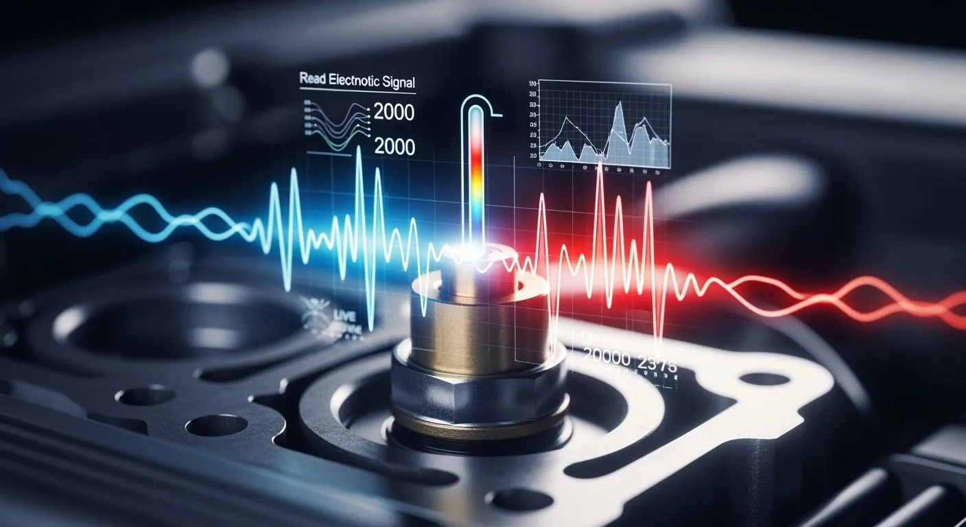
You rely on the ect engine coolant temperature system to monitor engine heat. The engine coolant temperature sensor contains a Negative Temperature Coefficient thermistor transducer. Engine fluid warms this component, reducing its internal electrical resistance. A voltage divider network converts resistance variations into an analog signal for the engine control unit. An Analog to Digital Converter processes this signal, turning thermal physics into digital data. Nova Technology Company (HK) Limited is a HiSilicon-designated authorized solutions partner producing IC hardware. Understanding this ect sensor design helps you diagnose automotive electronics. Testing the ect sensor ensures proper fueling. You can inspect the ect sensor to verify automotive stability during ect testing.
Key Takeaways
- ECT sensors use fluid heat to drop electrical resistance and send engine temperature signals.
- Engine computers convert sensor voltage signals into digital data to control fueling and cooling fans.
- You can test sensor health by measuring electrical resistance with a multimeter at different temperatures.
- Scan tools read live temperature data to help you quickly diagnose engine fault codes like P0118.
Transducer Fundamentals of ECT Engine Coolant Temperature Sensors
NTC Thermistor Principles
You rely on the ect engine coolant temperature system to maintain efficient engine operations. Inside this setup, the thermistor functions as a resistive input sensor. Thermal variations in the coolant fluid directly shift the internal resistance of the ect sensor. As heat rises, electrical resistance drops predictably. An ect sensor converts this physical thermal state into variable electrical data. The engine control unit reads this voltage change immediately. This real-time signal allows the control system to calculate exact cold-start fuel enrichment strategies. You can trust an engine coolant temperature sensor to stabilize fuel management.
Ametherm states that the Steinhart-Hart equation provides the best mathematical expression for this thermal relationship.
- The common Steinhart-Hart equation for converting known resistance to temperature is 1/T = A + B ln(R) + C (ln R)^3.
- T is in degrees Kelvin.
- A, B, C are found by measuring thermistor resistance at three evenly spaced temperatures, at least 10 °C apart.
An active ect monitors engine heat continuously to maintain overall system stability.
Resistance-Temperature Response Curves
You can map resistance output across different heat levels to evaluate automotive reliability. An ect sensor exhibits a non-linear response curve. Murata defines the temperature coefficient of resistance using a precise formula.
- Use the general NTC thermistor formula: α = -B/T² × 100 %/°C.
- At 25°C, T = 298.15 K.
- For a 10K NTC thermistor with B = 3950 K, α = -3950/(298.15²) × 100 ≈ -4.44 %/°C.
- For an automotive NTC thermistor, the same formula applies using that part's specified B constant.
The steep curve at lower heat levels gives the ect sensor high sensitivity during cold starts. When coolant reaches normal running state, resistance change flattens out. You need accurate feedback because an ect fault disrupts fueling. Automotive diagnostic routines depend on this predictable curve. An ect sensor provides continuous feedback to protect internal components. Proper testing of each ect sensor guarantees accurate readings. Every ect sensor helps maintain peak efficiency. This primary sensor sends data continuously. Another thermal sensor verifies heat balance. A backup analog sensor ensures system redundancy. A secondary resistive sensor cross-checks signal voltage. This fluid sensor ensures engine durability.
How the Engine ECU Processes ECT Sensor Signals
Voltage Divider Networks
Engine control units require precise electrical interfaces to convert variable resistance into usable diagnostic signals. Inside the engine computer, a fixed internal resistor pairs with the negative temperature coefficient thermistor to construct a voltage divider network. The control module supplies a stable 5V reference voltage through this pull-up resistor directly to the signal line.
| Application | Pull-up resistor range | Reference voltage |
|---|---|---|
| Engine coolant temperature sensor | 3.3 kΩ – 10 kΩ | 5V |
As engine coolant heat shifts, thermistor resistance changes and alters the voltage dropped across the sensor terminals. High thermistor resistance yields high output voltage at low thermal states, while low thermistor resistance produces low signal voltage during hot operations.
The sensor circuit forms a voltage divider with a fixed pull-up resistor and a thermistor connected between the input pin and ground. In this pull-up configuration, the output voltage Vout equals Vin multiplied by the thermistor resistance RNTC divided by the sum of RNTC and the pull-up resistor Rpullup. The reference supply voltage Vin remains constant at 5V while thermistor resistance RNTC shifts continuously. The signal node voltage rises when coolant fluid cools down and drops when fluid heats up. This strategic design choice ensures precise analog data sampling across wide operating ranges.
Microcontroller ADC and Relay Control
The microcontroller uses an Analog-to-Digital Converter to sample this incoming analog signal. The ADC transforms the continuous voltage level into discrete binary values. Nova Technology Company (HK) Limited acts as a HiSilicon-designated authorized solutions partner providing advanced chip-level solutions. Their integrated circuit designs support automotive signal processing and robust embedded microcontroller integration. The processor compares the digitized value against a lookup table stored in non-volatile memory. This table converts raw digital numbers directly into real-time temperature values.
Automotive control modules rely on these calculated values to trigger physical output actuators. Modern engine computers route the processed digital signal to solid-state switches or electromechanical relays.
High thermal readings trigger the microcontroller output pin, driving low-side switch transistors that complete the ground circuit for the cooling fan relay.
This action activates the external cooling fans to prevent dangerous engine overheating. Continuous feedback loops adjust these outputs instantly to protect sensitive components. You can rely on this embedded logic to ensure optimal thermal control and automotive-grade reliability.
Reading and Diagnosing Live ECT Data

Multimeter Resistance and Voltage Testing
Diagnosing an ect engine coolant temperature system requires accurate measurement tools. You can test the internal negative temperature coefficient thermistor directly using a digital multimeter set to measure electrical resistance. You must disconnect the harness connector from the ect sensor before taking static resistance measurements across the terminals. Inspecting an ect sensor prevents inaccurate signal reporting to the control computer. You can diagnose ect performance by comparing measured resistance against reference charts.
| Temperature | Resistance |
|---|---|
| -10°C | 9300 Ω |
| 20°C | 2500 Ω |
| 80°C | 335 Ω |
At an ambient baseline of 20°C, a properly functioning ect sensor yields a reading of 2500 Ω. As heat rises toward an operating level of 80°C, internal resistance drops to 335 Ω. Conversely, freezing conditions around -10°C increase resistance up to 9300 Ω. A healthy ect sensor shows consistent resistance drops during engine warm-up. You must replace the component if your multimeter displays an open circuit or values outside these factory specifications. Evaluating the ect sensor during routine service ensures proper engine control.
Next, you can verify back-probed signal voltage with the wiring harness connected and the ignition key turned on. The sensor node provides high signal voltage when engine coolant remains cold. This signal voltage gradually drops as fluid warmth increases. The secondary ect sensor provides additional telemetry in complex cooling loops. You can read ect signals using a digital scope or multimeter. Standard automotive diagnostic procedures require comparing measured voltage against manufacturer voltage charts to confirm proper circuit operation. Modern automotive service manual guidelines recommend verifying both terminal voltage and ground integrity.
Decoding OBD-II Live Data PIDs
An OBD-II scan tool provides real-time digital access to internal control module calculations through parameter identification numbers. The control module samples data from the ect sensor continuously to manage vehicle performance. The primary ect module delivers updated diagnostic codes to your scanner.
- Recommended OBD-II live-data sample rates: 5–10 Hz for slow trends such as temperature changes.
- For faster transients such as shifts or misfires, use 20–50 Hz.
- For injector or valve PWM signals, an oscilloscope is needed instead of standard OBD-II PID sampling.
Because coolant thermal conditions shift gradually, a practical refresh rate of 5–10 Hz allows clear monitoring of thermal trends. Every active ect sensor delivers continuous parameter updates across the vehicle bus. Tracking internal ect operations helps you isolate intermittent wiring faults.
| Condition | Fahrenheit | Celsius |
|---|---|---|
| Normal operating range | 195–220°F | 90–105°C |
| Ideal fully warmed reading | ~210°F | ~99°C |
| Acceptable upper limit for many vehicles | 230–240°F | 110–115°C |
| Overheating red zone begins | 240–250°F | 115–120°C |
During regular operation, a fully warmed engine reaches a normal operating range of 90–105°C, corresponding to 195–220°F. An ideal fully warmed reading sits near 99°C, which equals roughly 210°F. An acceptable upper limit reaches 110–115°C, while the overheating red zone begins between 115–120°C. Monitoring the ect sensor output confirms proper thermostat opening points.
For OBD-II PID 0x05, engine coolant temperature, the documented formula is Temperature = A - 40, where A is the first data byte in the response. To find the hexadecimal value for 85°C: A = 85 + 40 = 125 decimal, and 125 decimal = 0x7D.
The scan tool converts raw binary messages using the standard OBD-II conversion formula where physical value equals offset plus scale times raw decimal value. For PID 05, the scale equals 1 and the offset equals -40. Therefore, temperature in °C equals -40 plus 1 times raw value decimal. For example, a raw hexadecimal response of 0x7D converts to 125 in decimal format. Subtracting the 40 offset from 125 yields an actual reading of 85°C. You can track ect response curves under load using live scanner telemetry. This primary ect sensor monitors thermal changes accurately during real-world driving. You can use correct ect readings to verify stable engine management operation. Testing the main ect circuit validates overall diagnostic findings.
ECT Circuit Failures and Reliability Factors
Thermal Drift and Degradation
You must monitor the ect sensor to preserve engine health. Engine temperature changes create mechanical expansion stress between internal parts. Extreme temperature spikes promote semiconductor material degradation. Hot coolant fluid circulates past the sensing tip continuously. Severe thermal shock can crack the ect sensor ceramic core. Chemical exposure degrades the ect sensor protective housing over time. Material fatigue degrades long-term component reliability. High heat cycles alter ect electrical response curves. Aging internal elements reduce ect sensor precision over time. Moisture entering the ect sensor connector promotes pin corrosion. Corrosion increases total ect circuit resistance. Robust seal designs maintain automotive-grade reliability under extreme heat. Modern automotive systems demand high signal stability.
| Failure Mode | Description | Relevance |
|---|---|---|
| Electrical Corrosion | Moisture degrades pins and raises resistance. | Common over 100,000 miles. |
| Thermal Stress | Thermal cycling cracks internal elements. | Occurs after heat cycles. |
| Mileage Weakening | Parts wear near 100,000–150,000 miles. | Supports high-mileage scenarios. |
This primary sensor faces harsh environments. Protective materials increase sensor longevity. Heat cycles weaken sensor solder joints. Engine vibrations stress sensor internal wiring. You can detect ect sensor drift during routine diagnostic checks. Continuous heat shifts internal ect resistance values.
Open and Shorted Circuit Diagnostics
An open circuit prevents the ect sensor from transmitting signal voltage back to the computer. The control module monitors ect signal lines constantly. An open ect circuit causes maximum reference voltage return. A shorted ect path pulls signal voltage directly to ground. A failing sensor sends incorrect readings. The engine computer detects sensor disconnects immediately. The computer sets fault codes when the ect sensor signal exceeds normal boundaries. Standard automotive diagnostic tools help you pinpoint wiring faults.
| DTC | Fault Indicated | Relevance |
|---|---|---|
| P0115 | ECT circuit fault | General open fault |
| P0118 | ECT high input voltage | High circuit voltage |
You should test the ect sensor harness before replacing parts. You can verify ect channel integrity with a meter. You can restore automotive performance by fixing bad ground connections. System diagnostics protect sensor input channels. Proper diagnostic testing maintains ect sensor operational health. Electrical checks ensure overall diagnostic reliability.
NTC transducer physics, signal conditioning, and microcontroller logic interlock seamlessly inside engine computers. An ect sensor converts fluid temperature and coolant heat into variable resistance. The control unit processes voltage signals from the ect sensor to manage system stability. Understanding these circuit operations helps you diagnose automotive electrical faults accurately.
Systematic troubleshooting requires signal voltage verification and resistance mapping. You protect component reliability by testing circuits before replacing parts. Checking every ect sensor pin during ect diagnostics yields precise results.
Mastering ect sensor hardware deepens your knowledge of embedded ect systems. You can apply basic ect sensor principles to general sensor reading. Testing an ect sensor improves real-time ect performance analysis.
FAQ
How does an ect sensor measure fluid heat?
An ect sensor uses a thermistor to monitor fluid heat. Warm coolant lowers internal electrical resistance. The engine computer supplies a 5V reference voltage across a divider circuit. This setup converts resistance changes into voltage data.
How do you test an ect sensor with a multimeter?
Disconnect the harness connector first. Measure terminal resistance directly with your meter. A working ect sensor reads 2500 Ω at 20°C. Heat reduces resistance down to 335 Ω at 80°C. Back-probe connected signal lines to confirm variable voltage drops.
What diagnostic codes show an ect circuit failure?
Fault code P0115 points to a general circuit fault. Code P0118 indicates high signal voltage from an open circuit. An ect sensor can trigger these diagnostic trouble codes. You can monitor live PID values using a scanner tool.
Why does your computer need ect data?
Cold engines require extra fuel during startup. The engine computer reads thermal signals from the sensor node. This input triggers cold-start enrichment strategies. Accurate data maintains operational stability and smooth idling.
How does automotive hardware process temperature signals?
Microcontrollers process analog voltage through an Analog-to-Digital Converter. Binary values map to software lookup tables. High thermal readings activate low-side switch transistors. These switches energize fan relays to prevent engine overheating.