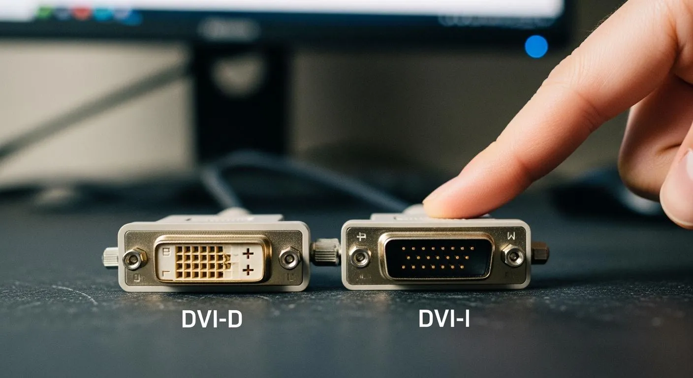
Starter Wire Diagram Best Practices for Electronic Hardware Connections
Starter wire diagram best practices ensure safe, reliable electronic hardware connections and minimize wiring errors for optimal system performance.
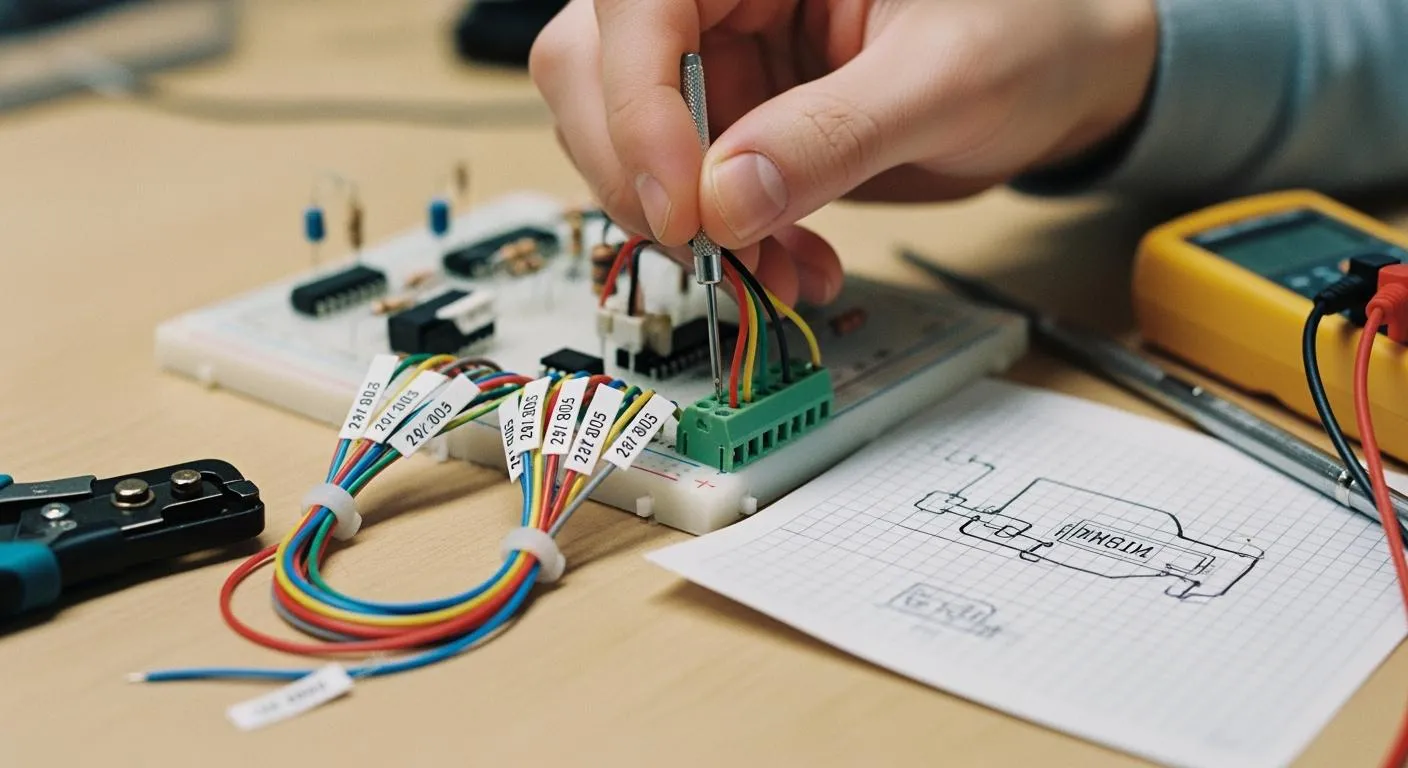
You need a clear understanding of a starter wire diagram to make safe and reliable electronic hardware connections. These diagrams serve as roadmaps that help you trace wires and pinpoint faults, making troubleshooting much easier for both new and experienced users. When you follow best practices, you protect your equipment and reduce the risk of costly mistakes.
| Benefit | Description |
|---|---|
| Regular Wiring Inspection | You can prevent unexpected breakdowns by checking all control wiring. |
| Safe Operation | Proper wiring ensures safe circuit operation and protects motors. |
| Long-lasting Performance | Good practices lead to durable and trouble-free system performance. |
Key Takeaways
- Understand starter wire diagrams to make safe and reliable electronic connections. They serve as essential roadmaps for troubleshooting.
- Follow best practices for wiring to prevent costly mistakes and ensure safe operation. Regular inspections can help avoid unexpected breakdowns.
- Use standardized symbols and clear labeling in diagrams. This practice reduces errors and improves safety during installation and maintenance.
- Prioritize safety by disconnecting the battery and using insulated tools. These precautions protect you from electrical hazards.
- Test connections with a multimeter to ensure proper operation. Regular testing helps identify issues early and maintains system reliability.
Understanding Starter Wire Diagram

A starter wire diagram helps you visualize how each part of an electronic starter system connects and works together. When you understand the main components and symbols, you can read and create diagrams with confidence. This skill makes troubleshooting much faster and more accurate.
Key Components and Symbols
You will find several key parts in every starter wire diagram:
- Battery: Supplies electrical power to the entire system.
- Starter Solenoid: Acts as a switch that controls the high current needed by the starter motor.
- Control Wire: Sends the signal from the ignition switch to the solenoid.
- Ignition Switch: Lets you start or stop the engine by controlling the flow of electricity.
- Relay: Protects the ignition switch from high current and ensures smooth operation.
- Ground Connection: Completes the circuit and safely directs excess current away.
You will also see common symbols in these diagrams:
- Ground symbol (three descending lines) shows where current exits safely.
- Switches (break in the line or 'T' shape) control electricity flow.
- Fuses (rectangle in a line) and circuit breakers (two circles with a line) protect against overloads.
- Connections (dots at line intersections) show where wires join.
Tip: Accurate diagrams help you quickly find faults and test components like relays and fuses. This reduces downtime and avoids guesswork.
Types of Starter Wire Diagrams
Starter wire diagrams come in different types, each with unique features. The two most common are series and parallel circuits.
-
Series Circuit:
- The same current flows through each component.
- If one part fails, the whole circuit stops working.
- Easier to wire and troubleshoot.
-
Parallel Circuit:
- Each component gets the same voltage.
- If one part fails, others keep working.
- Requires careful voltage matching to avoid problems.
| Advantages | Disadvantages |
|---|---|
| High starting current | High starting current may damage the motor |
| High starting torque | High inrush current causes voltage dip |
| Simplest controlling mechanism | High starting torque causes mechanical stress |
| Suitable for low power rated motors | No control over starting current and torque |
| Used in small applications like pumps | Only suitable for low rating motors |
When you use an accurate starter wire diagram, you save time during troubleshooting. You can spot wiring errors, test relays, and fix issues faster. This leads to safer and more reliable electronic hardware connections.
Designing Starter Wire Diagrams
Clarity and Accuracy
You need to design a starter wire diagram with clarity and accuracy to ensure safe and efficient electronic hardware connections. Clear diagrams help you avoid confusion and reduce errors during installation or troubleshooting. You should use universally recognized symbols and wiring conventions. This practice makes your diagrams easy to read and understand for anyone working on the system.
Tip: Always include every component in your schematic. Missing parts can lead to assembly mistakes and troubleshooting delays.
You can follow these best practices to improve clarity and accuracy:
- Label nets efficiently and use off-page connectors to show signal flow.
- Create standardized component symbols and assign reference designators.
- Run electrical rule checks and verify netlists to catch schematic errors.
- Choose a suitable page size for your circuit complexity.
- Name pages alphabetically for logical separation.
- Use a grid system to establish reference points.
- Add a title block in the footer with essential details.
- Place important notes or comments on separate pages.
- Track changes with a revision history.
- Include a table of contents for easy navigation.
You should maintain legibility by using clear, readable text. Monospaced fonts often work best. Arrange components and wires to avoid clutter. Avoid crossing wires unless necessary, and use visual indicators when they do.
Standardization and Labeling
Standardization and labeling play a key role in reducing wiring errors and improving safety. When you use standardized references and annotations, you make it easier for technicians to interpret the starter wire diagram. Proper labeling prevents costly mistakes and ensures compliance with industry regulations.
| Benefit/Consequence | Description |
|---|---|
| Faster Troubleshooting | 60-80% reduction in diagnostic time |
| Reduced Installation Errors | Prevents costly wiring errors during installation |
| Improved Safety | Enhances safety for technicians |
| Lower Maintenance Costs | Reduces lifetime maintenance expenses |
| Safety Hazards | Mislabeled circuits can lead to safety issues |
| Compliance Issues | Poor labeling can result in failed compliance audits |
Note: Standardized labeling helps you meet industry standards and pass compliance audits.
Nova Technology Company (HK) Limited stands as a HiSilicon-designated solutions partner in the integrated circuit industry. You benefit from their expertise in chip-level solutions, system integration, and advanced application scenarios. Their commitment to professional semiconductor practices ensures that your starter wire diagram meets the highest standards for clarity, accuracy, and reliability.
By following these guidelines, you create diagrams that support safe, efficient, and error-free electronic hardware connections.
Connecting to Electronic Hardware

Step-by-Step Procedures
You can connect a starter wire diagram to electronic hardware by following a clear sequence of steps. This process helps you achieve reliable and safe connections for your battery, solenoid, and control wire.
- Disconnect the vehicle’s battery to prevent electrical hazards.
- Mount the start engine switch securely in a convenient location.
- Run wires through the firewall to reach the engine bay.
- Make secure connections to the starter solenoid, ensuring tight terminals.
- Connect the control wire to the ignition power source.
- Finalize and secure your engine bay wiring, using cable ties or clamps.
- Test your new engine starter switch setup to confirm proper operation.
Tip: Always double-check your wiring diagram before making any connections. This step prevents errors and saves time during troubleshooting.
Safety and Error Prevention
You must prioritize safety when connecting starter wire diagrams. Simple precautions protect you from electrical shock and prevent accidental engine starts.
- Disconnect the battery before you begin work. This step eliminates the risk of electrical shock or fire.
- Use insulated tools to avoid accidental contact with live wires.
- Double-check your wiring diagram to reduce the risk of short circuits.
- Wear safety goggles to protect your eyes from sparks or debris.
- Work in a well-ventilated area, especially when handling lead-acid batteries.
Note: Careful preparation and attention to detail help you avoid costly mistakes and ensure safe operation.
Testing and Troubleshooting
Testing your starter wire diagram connections ensures that your system works as intended. You can identify and fix common wiring issues by following these steps:
- Perform a visual inspection. Look for visible damage, scratches, or breaks in the wiring path.
- Use a multimeter or continuity tester to check the conductivity of each wire. If you find a break, repair or replace the damaged section.
- Cross-probe using software tools to match schematic diagrams with physical locations on the circuit board.
You may encounter several common wiring issues during installation. The table below shows symptoms, possible causes, and solutions:
| Symptom | Possible Causes | Solutions |
|---|---|---|
| Complete Silence When Starting | Blown fuse in ignition circuit | Check and replace the fuse |
| Faulty ignition switch | Test and replace the ignition switch | |
| Broken control wire | Inspect and repair the control wire | |
| Bad ground connection | Ensure a solid ground connection | |
| Intermittent Starting Issues | Loose terminal connections | Tighten connections |
| Corroded wiring causing voltage drop | Clean and replace corroded wires | |
| Heat-sensitive component failure | Replace faulty components | |
| Worn ignition switch contacts | Replace worn contacts | |
| Continuous Cranking Problems | Stuck solenoid contacts | Replace the solenoid |
| Shorted control wire | Repair or replace the control wire | |
| Faulty ignition switch | Test and replace the ignition switch | |
| Welded solenoid contacts requiring replacement | Replace the solenoid |
You can also use basic diagnostic tests like continuity checks and voltage readings to assess the starter’s health. Inspect wiring connections for damage or corrosion. A troubleshooting checklist helps you identify issues such as worn-out contacts or malfunctioning relays.
Alert: Regular testing and maintenance keep your starter wire diagram connections reliable and safe.
Common Mistakes
You can avoid many problems if you recognize the most frequent mistakes made during starter wire diagram connections. These errors often lead to unreliable performance and make troubleshooting harder. Here are the mistakes you should watch for:
- Misinterpreting Symbols: You might confuse diagram symbols, which can cause incorrect installations.
- Missing Connections or Junctions: If you overlook a connection, the circuit flow breaks and the starter will not work.
- Incorrect Wire Sizing: Using the wrong wire gauge can result in overheating and damage to components.
- Overlapping Wires and Components: Cluttered diagrams increase the chance of wiring mistakes and make repairs difficult.
- Inadequate Labeling: Poor labeling leads to confusion when you try to fix or upgrade the system.
- Skipping the Review Process: If you do not review your diagram, you may miss errors that affect performance.
⚠️ Tip: Always double-check your diagram before connecting any wires. Careful review prevents costly mistakes.
How to Avoid Errors
You can prevent these mistakes by following simple best practices. Start by using clear and standardized symbols. Make sure every connection and junction appears in your diagram. Choose the correct wire gauge for each part of the circuit. Keep your layout organized to avoid overlapping wires. Label every wire and component so you can identify them easily during maintenance.
- Proper wiring standards ensure safe and correct functioning of electrical components.
- Ignoring these standards can cause electrical faults and increase downtime.
- A well-organized wiring layout prevents interference and maintains conductivity, which is essential for reliable performance.
| Mistake | Prevention Strategy |
|---|---|
| Mislabeling wires | Use clear, consistent labels |
| Incorrect connections | Follow the diagram step by step |
| Neglecting safety | Always disconnect power before work |
| Skipping review | Inspect and test before operation |
Note: You improve reliability and safety when you follow these best practices. You also make troubleshooting easier and faster.
If you pay attention to these details, you build starter wire diagrams that work well and last longer. You protect your hardware and make your job easier.
Tools and Resources
You need the right tools to create and test starter wire diagrams for electronic hardware projects. These tools help you build circuits, check connections, and ensure reliable performance. You can use the following essential items:
- Breadboard: Lets you prototype and build temporary circuits without soldering. You can quickly test different wiring setups.
- Digital Multimeter: Measures current, voltage, and resistance. You can troubleshoot wiring and verify circuit integrity.
- Test Leads (Alligator Clips): Connect components for testing circuits. You avoid soldering during early stages.
- Helping 3rd Hand: Holds circuit boards or wires steady when you solder or tin connections. You work more safely and accurately.
- Soldering Iron: Creates permanent circuits by soldering components together. You ensure strong and lasting connections.
Tip: Always keep your workspace organized. You reduce mistakes and make troubleshooting easier.
You also benefit from using specialized software and online resources for designing and troubleshooting starter wire diagrams. These tools help you create clear schematics and spot errors before you build your circuit.
- AutoCAD: A popular drafting utility for creating detailed schematics and wiring diagrams. You can design complex circuits with precision.
- promis•e draw: An add-in for AutoCAD that includes pre-constructed elements for electrical control design. You save time and improve accuracy.
| Tool/Resource | Purpose |
|---|---|
| Breadboard | Prototyping circuits |
| Digital Multimeter | Measuring electrical values |
| AutoCAD | Designing schematics |
| promis•e draw | Electrical control design |
Nova Technology Company (HK) Limited stands as a HiSilicon-designated solutions partner in the integrated circuit industry. You gain access to chip-level solutions, advanced system integration, and application scenarios tailored for professional semiconductor projects. Their expertise supports your starter wire diagram development, ensuring you meet industry standards for reliability and performance.
Note: Using the right tools and resources helps you build safer, more reliable electronic hardware connections. You improve your skills and achieve better results in every project.
You can achieve safe and reliable starter wire diagram connections by following these key steps:
- Read installation instructions for your specific motor starter.
- Identify and connect input terminals securely.
- Match output terminals to motor leads and check phase sequence.
- Test all wiring and starter coil operation before powering the motor.
- Check voltage and current ratings, ensure proper grounding, and use the right tools.
You improve your results by using software tools, starting with simple circuits, and regularly checking your work. Careful attention to detail and ongoing learning help you build accurate diagrams. Apply these best practices in your projects for better performance and safety.
FAQ
What is a starter wire diagram?
A starter wire diagram shows you how to connect each part of a starter system. You can use it to understand the flow of electricity and troubleshoot problems in electronic hardware.
Why should you use standardized symbols in diagrams?
Standardized symbols help you read and share diagrams easily. You avoid confusion and reduce mistakes when you follow industry standards.
How do you test starter wire connections?
You can use a digital multimeter to check voltage and continuity. Inspect each wire for damage. Test the starter switch and solenoid to confirm proper operation.
What safety steps should you follow before wiring?
Disconnect the battery first. Wear safety goggles and use insulated tools. Check your diagram and workspace for hazards. You protect yourself and your equipment.
Can you fix wiring mistakes without professional help?
You can fix simple mistakes by reviewing your diagram and checking connections. Use basic tools like a multimeter. For complex issues, ask a technician for help.