Step-by-Step Design Tutorial: Integrating an ADC Chip for Arduino Projects
Expert guide on Step-by-Step Design Tutorial: Integrating an ADC Chip for Arduino Projects. Technical specs, applications, sourcing tips for engineers and buyers.
Introduction
The integration of an Analog-to-Digital Converter (ADC) chip into Arduino projects is an essential skill for electronics engineers looking to expand the functionality of their microcontroller-based systems. ADCs are critical in converting analog signals from sensors into digital data that can be processed by the Arduino. With the growing demand for more precise and high-speed data acquisition in various applications, understanding how to effectively implement ADCs is crucial. In 2026, the global semiconductor revenue is projected to reach $595.2 billion, highlighting the increasing importance of efficient and innovative electronics design. This article will guide you through the process parameters, equipment, and common issues involved in integrating an ADC chip with Arduino, providing a comprehensive resource for both novice and experienced engineers.
Technical Overview
ADCs are integral components in bridging the gap between the analog world and digital systems. They work by sampling the voltage levels of analog signals and converting them into binary values that microcontrollers like Arduino can process. The resolution of an ADC, typically measured in bits, determines how fine the conversion can be. For instance, a 10-bit ADC can represent an analog input with 1024 discrete levels. Another critical parameter is the sampling rate, which dictates how often the ADC takes a sample of the input signal. The choice of ADC depends on the application requirements, such as the need for higher resolution or faster sampling rates. Common ADC types include successive approximation register (SAR), sigma-delta, and flash ADCs, each with its advantages and trade-offs. Integrating an ADC with Arduino involves selecting the right ADC chip, understanding its specifications, and ensuring proper communication and synchronization with the microcontroller.
Detailed Specifications
Table 1: Process Parameters & Tolerances
| Parameter | Value | Units | Notes |
|---|---|---|---|
| Resolution | 12 | bits | Higher resolution provides more precise data. |
| Sampling Rate | 1000 | SPS (Samples Per Second) | Depends on application requirements. |
| Input Voltage Range | 0-5 | V | Match with sensor output range. |
| Input Impedance | 10 | MΩ | Higher impedance reduces loading effects. |
| Power Supply Voltage | 3.3/5 | V | Ensure compatibility with Arduino. |
| Power Consumption | 5 | mW | Important for battery-operated devices. |
| Temperature Range | -40 to 85 | °C | Ensure operation in desired environment. |
| Offset Error | ±1 | LSB | Minimize for accurate measurements. |
| Gain Error | ±0.5 | % | Critical for precision applications. |
| Linearity Error | ±0.01 | %FSR | Full Scale Range error. |
| Noise | 1 | LSB | Lower noise improves signal clarity. |
Table 2: Equipment & Tools Required
| Equipment/Tool | Description | Notes |
|---|---|---|
| Arduino Board | Microcontroller platform | e.g., Arduino Uno or Mega |
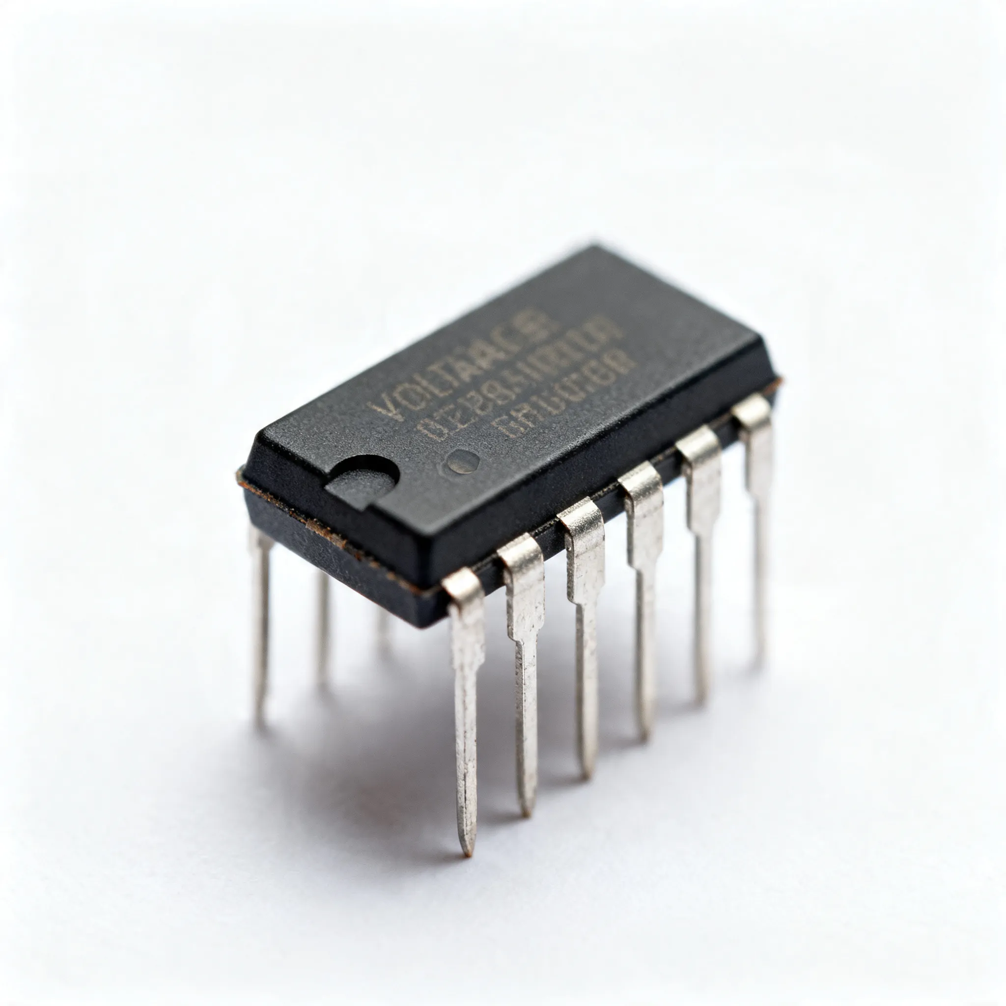
| ADC Chip | Analog-to-digital converter IC | e.g., MCP3008 |
| Breadboard | Prototyping board for circuit assembly | Ensure sufficient size for components |
| Jumper Wires | Connecting components on breadboard | Various lengths and types |
| Power Supply | Provides necessary voltage and current | Compatible with ADC and Arduino |
| Multimeter | Measures voltage, current, and resistance | Useful for troubleshooting |
| Oscilloscope | Visualizes signal waveforms | Optional, for detailed signal analysis |
| Soldering Iron | For permanent connections | Use with care |
| Software IDE | Arduino programming environment | Download from Arduino website |
Table 3: Common Issues & Solutions
| Issue | Solution | Notes |
|---|---|---|
| No Output Signal | Check power connections and ensure ADC is receiving power | Verify with multimeter |
| Inaccurate Readings | Calibrate the ADC and check for offset errors | Use known reference voltages |
| Noise in Signal | Use decoupling capacitors and shield cables | Reduce electromagnetic interference |
| Communication Errors | Check wiring and ensure correct SPI/I2C setup | Refer to ADC datasheet |
| Overheating | Ensure proper heat dissipation and check load conditions | Consider using heatsinks |
| ADC Not Detected | Verify connections and address settings | Check Arduino code for initialization |
Design Considerations
When integrating an ADC into an Arduino project, several design considerations must be addressed to ensure optimal performance. Firstly, the selection of the ADC chip is paramount. Consider the resolution and sampling rate required for your application. For example, a MCP3008 offers 10-bit resolution with 8 input channels, making it suitable for multi-sensor applications. The power supply voltage must match the ADC's requirements; most ADCs operate at 3.3V or 5V, compatible with Arduino platforms. It's crucial to ensure the input voltage range of the ADC aligns with the output range of the sensors used. Using voltage dividers or level shifters can help match these levels if needed.
Additionally, the communication protocol between the ADC and Arduino needs careful consideration. Common protocols include SPI and I2C, each with distinct advantages. SPI offers faster data rates, ideal for high-speed applications, while I2C is simpler and uses fewer connections, suitable for simpler setups. Ensure that the Arduino library supports the chosen protocol for seamless integration.
Noise and interference are other critical factors. Minimizing noise involves using proper grounding techniques, shielding cables, and placing decoupling capacitors near the ADC's power pins. These steps help ensure the accuracy and reliability of the data collected. Finally, consider the operating environment. If the system will be exposed to extreme temperatures, select an ADC with a suitable temperature range to prevent performance degradation.
Step-by-Step Guide
Follow these detailed steps to integrate an ADC chip into your Arduino project:
- Select the ADC: Choose an ADC like the MCP3008, considering resolution and channel requirements. Check the datasheet for specifications and pin configurations.
- Prepare the Breadboard: Insert the ADC chip onto the breadboard. Connect the power supply, ensuring the correct voltage level for the ADC.
- Wire the ADC to Arduino: Use jumper wires to connect the ADC to the Arduino. For SPI communication, connect the MISO, MOSI, SCK, and CS pins to the corresponding Arduino pins.
- Connect Sensors: Attach the sensor outputs to the ADC input channels. Ensure the sensor output voltage does not exceed the ADC's input range.
- Install Necessary Libraries: In the Arduino IDE, install libraries required for ADC communication. For SPI, use the SPI.h library.
- Write the Arduino Code: Develop the code to initialize the ADC and read data from the input channels. Use the library functions to facilitate communication.
- Test the Setup: Upload the code to the Arduino and monitor the serial output. Verify the ADC readings against known values to ensure accuracy.
- Troubleshoot: If issues arise, refer to the common issues table for solutions. Check all connections and ensure the code is correct.
Common Issues & Solutions
Integrating an ADC can present challenges. Here are some common issues and their solutions:
- No Output Signal: Ensure the ADC is powered and that all connections are secure. Use a multimeter to check voltage levels.
- Inaccurate Readings: Calibrate the ADC using reference voltages. Check for offset and gain errors and adjust in software if needed.
- Noise in Signal: Add decoupling capacitors near the ADC's power pins and use shielded cables to reduce interference.
- Communication Errors: Double-check the wiring and protocol setup. Ensure the correct library is used in the Arduino code.
- Overheating: Verify that the ADC is not overloaded. Consider adding heatsinks or improving ventilation.
Applications & Use Cases
ADCs are used in various applications, from simple sensor data acquisition to complex signal processing. In home automation, ADCs can monitor temperature, light, and humidity levels, providing input for smart systems. In industrial settings, ADCs facilitate precise control and monitoring of machinery, ensuring optimal performance and safety. Medical devices also rely on ADCs for accurate readings of vital signs, such as ECG and blood pressure measurements. By converting analog signals into digital data, ADCs enable the integration of a wide range of sensors into Arduino projects, expanding their functionality and potential applications.
Selection & Sourcing Guide
When selecting an ADC, consider the specific requirements of your project. Factors such as resolution, sampling rate, and communication protocol are critical. The MCP3008 is a popular choice for its 10-bit resolution and 8-channel input, ideal for multi-sensor applications. To source ADCs, visit IC Online, where you can find a wide range of components with competitive pricing and fast delivery. Ensure you compare specifications and prices to find the best fit for your project.
FAQ
- What is an ADC? An ADC, or Analog-to-Digital Converter, converts analog signals into digital data for processing by microcontrollers like Arduino.
- Why do I need an ADC? ADCs are necessary for interfacing analog sensors with digital systems, enabling data acquisition and processing.
- What resolution do I need? The resolution depends on the precision required for your application. Higher resolution provides more detailed data.
- How do I reduce noise in my ADC readings? Use decoupling capacitors, proper grounding, and shielded cables to minimize noise and interference.
- What communication protocols are available for ADCs? Common protocols include SPI and I2C, each with distinct advantages depending on speed and complexity needs.
- Can I use multiple ADCs with one Arduino? Yes, multiple ADCs can be connected using different communication channels or multiplexing techniques.
- How do I calibrate my ADC? Use known reference voltages to adjust offset and gain errors, ensuring accurate readings.
- What happens if the ADC input exceeds its range? The ADC may produce inaccurate readings or become damaged. Use voltage dividers or level shifters to match input levels.
- How do I choose the right ADC for my project? Consider resolution, sampling rate, input range, and communication protocol to match your project's requirements.
Conclusion
Integrating an ADC chip into Arduino projects enhances their capabilities, allowing for precise data acquisition and processing from a variety of sensors. Understanding the technical specifications, design considerations, and common challenges is vital for successful implementation. By following the step-by-step guide and utilizing the resources available, engineers can effectively incorporate ADCs into their projects, unlocking new possibilities in electronics design and innovation.