A Comprehensive Look at Capacitor ESR for Modern Electronics in 2026
Capacitor ESR creates internal power loss, thermal stress, and voltage ripple. Understand its impact and master measurement methods for optimal power design.
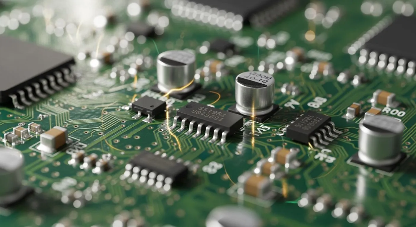
You define equivalent series resistance as the dynamic internal resistive element in capacitors that impedes AC current flow. Modern 2026 electronics rely on low capacitor esr to maximize power supply efficiency, optimize thermal management, and maintain system reliability. High esr generates unwanted heat through power loss, introduces high-frequency output noise, and demands precise measurement setups. As a HiSilicon-designated solutions partner, Nova Technology Company (HK) Limited delivers advanced chip-level solutions to solve these critical hardware challenges.
Key Takeaways
- Low ESR capacitors maximize power efficiency and reduce voltage ripple in modern electronics.
- Excessive internal resistance generates heat and shortens the operational lifespan of capacitors.
- Precision meters use low-voltage signals to measure capacitor resistance accurately on circuit boards.
- Engineers connect identical capacitors in parallel to lower total resistance and boost stability.
Understanding Equivalent Series Resistance (ESR)

What Is Capacitor ESR?
Every real-world capacitor contains non-ideal internal resistance alongside its pure capacitive property. You call this non-ideal characteristic the equivalent series resistance. While a capacitor primary job centers on dynamic energy storage, internal physical elements create opposition to alternating current flow.
For ceramic and solid electrolytic capacitors, specific physical structures directly build up this unwanted internal resistance:
- Electrodes: The metallic resistance within conductive internal plates or electrode layers.
- Leads: The resistance originating from internal metallic connection wires and leads.
- Dielectric Material: Energy losses occurring inside the dielectric medium itself during signal changes.
Understanding these physical sources helps you choose better components for modern chip-level power supplies. As a HiSilicon-designated solutions partner, Nova Technology Company (HK) Limited helps hardware engineering teams analyze internal component parasitics to optimize complex integrated circuit designs and system stability.
Impact on Voltage Ripple and Power Loss
In switched-mode power supplies (SMPS), capacitor esr plays a huge role in output power quality. High switching currents pass through output filtering caps continuously. The voltage ripple across an output cap combines pure capacitive ripple with an esr voltage drop. You calculate this dynamic voltage drop using a simple formula:
$$\Delta V_{ESR} = \Delta I_L R_{ESR}$$
The inductor current changes polarity during switching operations. Output capacitor esr introduces a sharp step-like voltage feature at these transitions. This resistive voltage jump often exceeds the pure capacitive voltage ripple. In real-world circuit layouts, parasitic resistance typically dominates your total high-frequency output ripple.
Different dielectric technologies deliver distinct performance profiles in buck converter designs:
| Capacitor Technology | ESR Characteristics | Impact on High-Frequency Voltage Ripple |
|---|---|---|
| Aluminum Electrolytic | Excessively high esr across temperature | Results in significantly higher output ripple voltage. |
| Tantalum-Polymer / Tantalum-MnO2 | Low esr at switching frequency | Achieves low output ripple voltage with stable operation. |
| MLCC (Multilayer Ceramic) | Extremely low esr | Can induce feedback loop instability, causing high ripple due to oscillations. |
Selecting an ultra-low esr ceramic capacitor might seem optimal at first glance. However, extremely low resistive values remove phase margin from power management feedback loops. You must carefully balance resistance values to prevent control loop instability and unwanted supply noise.
Thermal Failure and Component Degradation
Current flowing through internal resistance generates unexpected heat inside the component winding or ceramic layers. High esr causes power dissipation directly inside the capacitor package according to the fundamental electric power law:
$$P = I_R^2 \cdot ESR$$
This continuous thermal dissipation stresses the internal component structure severely. Heat buildup impacts wet aluminum electrolytic capacitors worse than solid state devices through a three-step failure process:
- Power Loss and Heat Generation: Ripple current flowing through internal resistance causes power loss, generating heat directly inside the capacitor winding core.
- Temperature-Driven Evaporation: Heat increases the evaporation rate of liquid electrolyte through rubber end-seals.
- Exponential Acceleration: Heat accumulation speeds up electrolyte loss; every $10\text{ }^\circ\text{C}$ temperature increase doubles the evaporation rate, halving operational lifespan.
Internal thermal stress from Equivalent Series Resistance (ESR) is calculated via ripple current heating: ΔT = I_ripple² * ESR * R_thermal. This elevation in core temperature accelerates the Arrhenius degradation rate, leading to a shortened operational lifetime.
You can calculate the shortened operating lifespan using the standard Arrhenius rule of thumb:
$$L = L_{rated} \cdot 2^{\frac{T_{rated} - T_{core}}{10}}$$
Excessive core heat degrades internal electrolyte, increases component resistance further, and quickly triggers catastrophic circuit failure.
Key Factors Influencing Capacitor ESR
Different operating conditions directly alter capacitor esr in modern hardware layouts. You must evaluate these key factors to maintain reliable circuit performance.
Dielectric Material Performance
Dielectric materials react differently under electrical stress. Class 2 ferroelectric ceramics like X7R experience severe changes when you apply a DC bias voltage:
- Ferroelectric Dipole Alignment: Applying a DC bias voltage generates an electric field that aligns dipoles within the ferroelectric material.
- Permittivity Drop: Dipole alignment decreases the incremental permittivity of the dielectric.
- Capacitance Loss: You observe a capacitance drop between 10% and 90% at the component's rated voltage.
This physical phenomenon changes electrical behavior across operating frequencies:
| Parameter / Behavior | Condition / Mechanism | Impact under DC Bias |
|---|---|---|
| Layer Field Intensity | Reduced dielectric layer thickness increases layer counts. | You get higher electric field strength across individual layers for a given voltage. |
| ESR Variation Below SRF | Parallel dielectric losses dominate total component loss. | Lower capacitance reduces parallel conductance, transforming into a higher esr. |
| ESR/ESL At or Above SRF | Inductive and high-frequency resistive behaviors dominate. | Terminal voltage changes do not alter esr values at or above the self-resonant frequency. |
Frequency and Temperature Dependency
Operating temperature heavily affects internal resistive losses. In freezing or low-temperature environments, aluminum electrolytic capacitors experience an increase in their esr, which consequently affects the overall impedance behavior of the component. Cold liquid electrolyte turns sluggish, elevating overall internal resistance.
Frequency also changes overall resistance. High AC signal frequencies push electric current toward the outer conductor surface through the skin effect. You will notice esr shifting constantly as operating frequencies move away from the self-resonant point.
Component Aging Effects
Capacitors degrade over time through continuous thermal and electrical stress. Liquid electrolytes inside aluminum caps slowly evaporate through seal cracks over time. This electrolyte loss increases internal esr gradually. You must monitor component aging closely to prevent unexpected power supply failures and maintain system stability.
Measuring ESR in Circuit Assemblies
Accurate testing helps you detect degraded components before system failure occurs. You can measure internal resistance using several standard laboratory tools.
LCR Meters and Dedicated ESR Testers
Benchtop equipment and field tools use different test frequencies to evaluate capacitor esr.
| Equipment Type | Standard Test Frequencies | Application / Notes |
|---|---|---|
| Benchtop LCR Meters | 50 Hz to 1 MHz | Flexible signal range tailored to specific component specs |
| Portable ESR Meters | Fixed 100 kHz | Designed primarily for fast pass/fail screening |
Precision meters rely on four-wire Kelvin sensing to ensure accurate low-level esr readings:
- Mitigation of Parasitic Effects: It prevents distortion in precision impedance readings by reducing parasitic inductance and lead resistance.
- Compensation for Voltage Drops: It bypasses errors induced by contact resistance, ensuring accurate voltage sensing directly at the device.
Oscilloscope and Function Generator Setup
You can set up a custom measurement bench without a dedicated meter. First, configure a function generator to inject a high-frequency AC square or sine wave through a known reference resistor into your component. Next, connect an oscilloscope probe directly across the capacitor terminals.
At high frequencies, pure capacitive reactance drops near zero. The remaining voltage waveform on your oscilloscope screen reflects the resistive drop across internal structures. You then calculate esr by dividing this peak voltage reading by the AC current passing through the circuit.
In-Circuit Testing Considerations
Testing components directly on a printed circuit board creates practical measurement challenges. Parallel impedance paths on the PCB alter your target readings. Nearby active ICs, inductors, and low-value resistors absorb test currents and lower the measured resistance.
Low-voltage test signals below 0.3 volts prevent nearby silicon diodes and transistor junctions from turning on during in-circuit testing.
You must select test equipment that uses small signal amplitudes. This approach prevents parasitic parallel paths from masking elevated esr values during board diagnostics.
Circuit Design Strategies Using Low-ESR Capacitors
Component Selection for High-Frequency SMPS
You need smart filtering choices when building modern power electronics systems. Switched-mode power supplies operate at fast switching speeds. High esr degrades converter efficiency by dissipating power as heat. Selecting the right capacitor esr reduces temperature buildup and keeps your voltage rails stable. As a HiSilicon-designated solutions partner, Nova Technology Company (HK) Limited provides advanced IC design assistance to optimize chip-level power delivery networks.
Parallel Capacitor Configurations
Engineers often connect multiple capacitors in parallel to achieve a lower overall resistance. However, combining different component values creates sharp anti-resonance spikes. Placing mismatched components in parallel causes specific circuit issues:
- Sharp spikes in net impedance where capacitive and inductive properties interact
- Amplification of circuit noise and potential voltage overshoots
- Elevated stress on power switching components
- Necessity for larger, more complex EMC filters
- Increased reactive currents leading to thermal overheating in snubber capacitors and degraded system efficiency
You must match component values carefully to prevent unexpected parasitic oscillations across your circuit board layout.
Decoupling Power Distribution Networks
You can target low impedance across high operating frequencies by tuning your decoupling network. Selecting identical parallel ceramic components suppresses parasitic resistance without creating sharp resonance peaks.
| Design Technique | Underlying Principle / Formula | Design Impact |
|---|---|---|
| Target Impedance & ESR Matching | $\text{Target Impedance} = \frac{\text{Max Allowable Voltage Ripple}}{\text{Max Instantaneous Current}}$ Capacitance: $C = \frac{L}{R^2}$ | Align esr closely with target impedance to keep the impedance curve flat across frequencies. |
| Identical Parallel Capacitors | Arraying identical low-esr ceramic caps (e.g., $0.01\mu\text{F}$ to $0.1\mu\text{F}$) | Prevents unwanted resonance peaks and impedance discontinuities caused by mixing different values. |
| Inductance Reduction | Connecting multiple capacitors in parallel | Inversely reduces total connection/parasitic inductance; smaller packages (0201/0402) lower ESL. |
| High-Frequency Tuning | Selecting components with higher SRF (2–3x operating frequency) | Ensures effective noise filtering before entering inductive region; supported by power planes for ultra-high frequencies. |
Proper layout choices keep total impedance flat. This approach protects sensitive digital chips from power noise.
Managing capacitor esr requires balancing power efficiency, component cost, and board space. Selecting ultra-low resistance ceramics improves ripple filtering, but it can destabilize power supply feedback loops. You must evaluate design trade-offs to keep your regulators stable.
- Consult IC datasheets to verify minimum resistance thresholds.
- Add external series resistors during bench tests to plot stability curves.
- Inject artificial ripple signals into constant on-time controllers when natural resistance drops too low.
Always validate ceramic dielectrics across temperature changes and dynamic loads to ensure long-term hardware reliability.
FAQ
How do you choose between MLCCs and tantalum capacitors for power filtering?
You should evaluate your circuit switching frequency and ripple tolerance. MLCCs offer lower impedance at high frequencies. However, tantalum capacitors provide stable capacitance under high DC bias voltage. Compare both options against your target feedback loop stability requirements.
Why does capacitor esr increase at extremely low operating temperatures?
Cold environments freeze or thicken liquid electrolyte inside wet capacitors. This physical change increases internal ionic resistance significantly. You can select solid polymer or ceramic components to maintain low esr values during cold temperature operations.
Can you measure capacitor resistance directly on a populated circuit board?
You can perform in-circuit measurements using specialized meters. Always set your test signal voltage below 0.3 volts. Low voltages prevent nearby semiconductor junctions on the circuit board from turning on and distorting your readings.
What happens when you put identical capacitors in parallel?
You divide total resistance while increasing overall capacitance. Parallel layouts lower power dissipation and help reduce output voltage ripple. Place identical components close together to minimize unwanted parasitic inductance across your power delivery network.