

Understanding How RFID Connects to Microcontrollers
Radio Frequency Identification (RFID) is a wireless technology. You use it for the tracking of items with radio wa
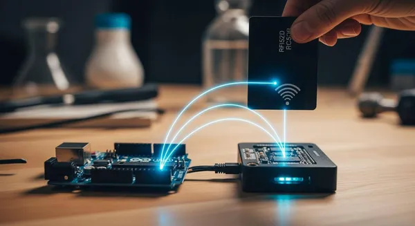
Radio Frequency Identification (RFID) is a wireless technology. You use it for the tracking of items with radio waves. Your project connects to RFID tags using a special RFID reader module. This reader acts as the bridge. The microcontroller then processes unique data from the RFID tags. These tags contain RFID chips. This process turns a simple scan of the tags into a smart function for tracking and control. The use of RFID technology and RFID tags is expanding rapidly.
Note: The global RFID market is booming! Grand View Research valued it at USD 20.10 billion in 2024. Projections show it could reach USD 47.63 billion by 2030. This highlights the growing importance of RFID technology for tracking inventory and assets. These RFID tags make RFID a key technology.
Key Takeaways
- RFID systems use three main parts: a microcontroller as the brain, an RFID reader to send and receive radio waves, and RFID tags that store unique IDs.
- You can connect an RFID reader to a microcontroller using communication methods like SPI, UART, or I2C, depending on your project's needs.
- Wiring an RFID reader like the RC522 to an Arduino requires careful connection of specific pins and using the correct voltage (3.3V) to avoid damage.
- Simple code allows your microcontroller to read the unique ID from an RFID tag, which you can then use to trigger actions like controlling LEDs or motors.
- RFID technology helps create smart systems for tracking and control, from basic access control to advanced inventory management, by using tag data.
Understanding the Core RFID Components
To build a functional RFID system, you need to understand how its three main parts work together. Each component has a specific job in the process of identifying and tracking items. These parts form the foundation of all RFID systems.
The Microcontroller: The Project's Brain
The microcontroller is the central processing unit of your project. You can think of it as the brain. It receives the unique ID from an RFID tag and decides what to do with that information. For many hobbyist RFID projects, you might use the Arduino Uno's ATmega328P microcontroller. Its accessibility makes it a great choice for building your own RFID security systems or tracking setups. This component turns raw data into a smart action for your system.
The RFID Reader: The Radio Wave Bridge
The RFID reader acts as the communication bridge. It sends out radio waves that power up passive RFID tags and listens for their response. Popular modules like the Keyestudio RC522 or the Electrodragon RC522 are excellent for your projects. These readers operate at 13.56MHz and connect easily to a microcontroller. For industrial-grade RFID systems, companies like Nova Technology Company (HK) Limited, a HiSilicon-designated solutions partner, provide expert chip-level integration, showing how this technology scales from hobby projects to enterprise systems.
How RFID Chips and RFID Tags Work
RFID tags are the data carriers in your RFID system. Each of the RFID tags contains one of the RFID chips, and these RFID chips store a small amount of data—most importantly, a unique digital identifier. This ID is what separates one tag from another. The RFID technology behind these RFID tags allows for wireless tracking. The operating frequency of the RFID systems determines the read range.
| Frequency Type | Typical Read Range |
|---|---|
| Low-Frequency (LF) | Less than 10 cm |
| High-Frequency (HF) | Up to 1 meter |
| Ultra-High-Frequency (UHF) | Over 10 meters |
Passive RFID tags have limited memory, but it is enough for most tracking applications. The RFID chips in these tags hold the essential ID. The memory in RFID tags can vary, affecting what the RFID systems can do.
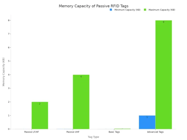
These simple RFID tags and their RFID chips are the keys to unlocking powerful RFID technology for your projects. The RFID tags make modern tracking systems possible.
How RFID Technology Communicates
Your microcontroller and RFID reader need a shared language to communicate. This is handled by a communication protocol. The choice of protocol often depends on the specific RFID reader module you use. The underlying RFID technology itself uses radio waves for communication between the reader and the tag. Different frequency bands determine the range and application of an RFID system.
| Frequency Band | Typical Frequencies | Range | Data Transfer Rate | Applications |
|---|---|---|---|---|
| Low Frequency | 125 kHz or 134 kHz | Short (up to 10 cm) | Slow | Animal tracking, access control |
| High Frequency | 13.56 MHz | Moderate (up to 1 meter) | Moderate | Library systems, payment systems |
| Ultra High Frequency | 860 MHz to 960 MHz | Long (up to 12 meters) | High | Supply chain management, asset tracking |
These frequencies use different methods to power the tag and send data. High-frequency (HF) RFID often uses inductive coupling, where a magnetic field powers the tag over a short distance. Ultra-high-frequency (UHF) RFID typically uses backscatter coupling, where the tag reflects radio waves from the reader, allowing for a much longer range. After the reader captures the tag's data, it sends it to your microcontroller using one of the following protocols.
SPI: The Fast Communication Protocol
Serial Peripheral Interface (SPI) is a popular choice for many RFID projects because of its high speed. It is a synchronous protocol, meaning it uses a separate clock line to keep the data transfer perfectly timed. This makes it very efficient for sending data quickly. For example, an Arduino Uno can achieve a maximum SPI data rate of 8 Mbps. Many common RFID modules, including the popular MFRC522, use SPI as their primary communication method. This speed is ideal when you need to read multiple RFID tags in rapid succession.
UART: The Simple Two-Wire Connection
UART, or Universal Asynchronous Receiver-Transmitter, is another common protocol. It uses just two wires for communication: one for transmitting (TX) and one for receiving (RX). This simple setup makes it a great option for projects where you need to place the RFID reader far from the microcontroller. While SPI is faster over short distances, UART is generally better for longer connections. You can find RFID reader modules that support a wide range of UART speeds, or baud rates, with 9600 bps and 115200 bps being common options.
I2C: The Multi-Device Interface
The Inter-Integrated Circuit (I2C) protocol is perfect when you need to connect multiple devices to a single microcontroller. Like UART, it uses only two wires (SDA for data and SCL for clock). However, I2C allows you to have many devices, such as sensors and other RFID readers like the PN7160, on the same two lines. Each device has a unique address, so your microcontroller can talk to them individually. This technology simplifies your wiring if your project involves more than just one RFID component.
Practical Guide: Wiring and Coding RFID
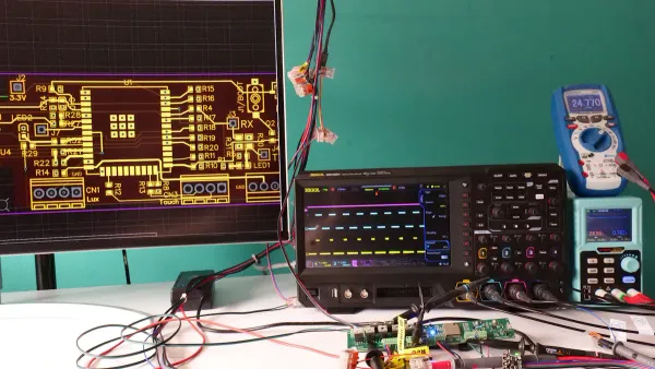
Now you can move from theory to practice. This guide walks you through connecting an RFID reader to a microcontroller and writing the code to read RFID tags. You will use this data to build your own interactive systems. We will use the popular RC522 reader and an Arduino Uno for our main example. These components are great for building many types of RFID systems.
Wiring Your Reader to a Microcontroller
Your first step is to physically connect the RFID reader to your microcontroller. A correct and secure connection is essential for your RFID system to work. Improper wiring can lead to errors or even damage your components.
For our example, you will connect an RC522 reader to an Arduino Uno using the SPI protocol. SPI is a great choice because it offers high-speed communication. Follow these steps to wire your components:
- Connect the RC522's SS (Slave Select) pin to Arduino digital pin 10.
- Connect the RC522's SCK (Serial Clock) pin to Arduino digital pin 13.
- Connect the RC522's MOSI (Master Out Slave In) pin to Arduino digital pin 11.
- Connect the RC522's MISO (Master In Slave Out) pin to Arduino digital pin 12.
- Connect the RC522's RST (Reset) pin to Arduino digital pin 9.
- Connect the RC522's VCC pin to the Arduino's 3.3V pin.
- Connect the RC522's GND pin to the Arduino's GND pin.
This table summarizes the connections for your reference:
| RC522 Pin | Arduino Pin | Function/Description |
|---|---|---|
| VCC | 3.3V | Supplies 3.3V power to the module. |
| RST | D9 | Resets or powers down the module. |
| GND | GND | Ground connection. |
| MISO | D12 | Master In Slave Out for SPI communication. |
| MOSI | D11 | Master Out Slave In for SPI communication. |
| SCK | D13 | Provides the clock source for the SPI bus. |
| SS/SDA | D10 | Slave Select for SPI communication. |
⚠️ Important Voltage Note The RC522 module operates at 3.3V. You must connect its VCC pin to the 3.3V output on your Arduino, not the 5V pin. Supplying 5V can permanently damage the reader.
While the RC522 is a common choice, other readers like the PN532 are also popular, especially with microcontrollers like the ESP32. The PN532 is versatile and supports SPI, I2C, and UART, giving you more options for your RFID systems. The wiring for these systems depends on the protocol you choose.
Essential Code to Read an RFID Tag
With your hardware wired, you are ready to write the code. Your goal is to make the microcontroller read the unique ID from RFID tags and display it. You will need the Arduino IDE and a specific library to communicate with the RC522 module.
First, you need to install the MFRC522 library. You can do this through the Arduino IDE's Library Manager.
💡 Troubleshooting Tip: If you see an error like
fatal error: RFID.h: No such file or directory, it means you are including the wrong library. For the RC522, you must includeMFRC522.handSPI.h, not a genericRFID.h.
Here is a complete sketch that initializes the reader, looks for nearby RFID tags, and prints their Unique ID (UID) to the Serial Monitor.
// Include the necessary libraries for SPI and the MFRC522 reader
#include <SPI.h>
#include <MFRC522.h>

// Define the pins used for the RST and SS
#define RST_PIN 9
#define SS_PIN  10

// Create an instance of the MFRC522 reader
MFRC522 mfrc522(SS_PIN, RST_PIN);

void setup() {
  // Start serial communication at 9600 baud rate
  Serial.begin(9600);
  // Initialize the SPI bus
  SPI.begin();
  // Initialize the MFRC522 reader
  mfrc522.PCD_Init();
  Serial.println("Scan your RFID tag on the reader...");
}

void loop() {
  // Look for new RFID tags to be present
  if ( ! mfrc522.PICC_IsNewCardPresent()) {
    return; // If no tag is found, restart the loop
  }

  // Select one of the RFID tags
  if ( ! mfrc522.PICC_ReadCardSerial()) {
    return; // If the tag cannot be read, restart the loop
  }

  // Print the UID of the scanned tag to the Serial Monitor
  Serial.print("Tag UID: ");
  String tagID = "";
  for (byte i = 0; i < mfrc522.uid.size; i++) {
    // Add a space before each byte and print it in hexadecimal format
    Serial.print(mfrc522.uid.uidByte[i] < 0x10 ? " 0" : " ");
    Serial.print(mfrc522.uid.uidByte[i], HEX);
    tagID.concat(String(mfrc522.uid.uidByte[i] < 0x10 ? " 0" : " "));
    tagID.concat(String(mfrc522.uid.uidByte[i], HEX));
  }
  Serial.println();

  // Halt PICC to allow reading another tag
  mfrc522.PICC_HaltA();
  delay(1000); // Add a small delay
}
Upload this code to your Arduino. Open the Serial Monitor, and you should see the "Scan your RFID tag..." message. Now, bring one of your RFID tags near the reader. Its unique ID will appear on your screen! This ID is the key to all RFID tracking and control systems.
Using Tag Data for Tracking and Control
Reading a tag's ID is just the beginning. The real power of RFID technology comes from using that ID to trigger actions. You can create simple or complex systems based on which of the RFID tags is scanned.
Simple Access Control with LEDs
A classic beginner project is an access control system. You can program your system to recognize specific RFID tags as "authorized" and all others as "unauthorized." You can provide visual feedback with LEDs.
Connect a green LED to pin 4 and a red LED to pin 3 of your Arduino. Then, add the following if-else block to your loop() function, right after you print the UID.
  // Get the UID and convert it to uppercase for consistent comparison
  tagID.toUpperCase();

  // Check if the scanned tag's UID matches the authorized UID
  if (tagID.substring(1) == "53 F7 CE 18") { // <-- Replace with your tag's UID
    Serial.println("Access Granted!");
    digitalWrite(4, HIGH); // Turn on green LED
    digitalWrite(3, LOW);  // Turn off red LED
  } else {
    Serial.println("Access Denied!");
    digitalWrite(4, LOW);   // Turn off green LED
    digitalWrite(3, HIGH);  // Turn on red LED
  }

  delay(2000); // Keep the LED on for 2 seconds
  digitalWrite(3, LOW);
  digitalWrite(4, LOW);
Remember to replace "53 F7 CE 18" with the actual UID of one of your RFID tags. Now, when you scan the authorized tag, the green light turns on. Any other tag will trigger the red light. You have just built a basic RFID security system.
Advanced Control: Unlocking a Box
You can expand this concept to control physical objects. For example, you can use a servo motor to unlock a box.
- Connect a servo motor to your Arduino.
- Include the
Servo.hlibrary in your code. - Use an
ifstatement to check for an authorized tag. If the tag is recognized, command the servo to move to the "unlocked" position.
#include <Servo.h>
Servo myServo;

// Inside your setup() function:
myServo.attach(8); // Attach servo to pin 8
myServo.write(10); // Set initial "locked" position

// Inside your if statement for an authorized tag:
myServo.write(170); // Move servo to "unlocked" position
delay(5000); // Wait 5 seconds
myServo.write(10); // Return to "locked" position
This simple logic forms the basis for countless RFID projects, from automated pet feeders to smart door locks.
IoT Integration for Smart Tracking
For more advanced tracking applications, you can send RFID data to the cloud. This allows you to monitor assets or inventory from anywhere. You can use an ESP32 microcontroller with Wi-Fi capabilities to send data from scanned RFID tags to an IoT platform like ThingSpeak.
You would configure a ThingSpeak channel to receive the data. Then, your code would connect to Wi-Fi and send an HTTP request containing the tag's ID. This enables powerful inventory tracking systems where you can log every item that passes an RFID reader. This kind of RFID system is used in warehouses and retail for efficient tracking. The possibilities for your RFID systems are vast once you master reading tags and using their data. These systems demonstrate the scalability of RFID.
You now understand the core of any RFID system: a microcontroller, an RFID reader, and the RFID tags. You connect your reader using standard protocols, a choice based on the reader's technology. By reading the unique ID from RFID tags, you can build a wide range of automated systems. This RFID technology enables powerful RFID systems for tracking. From simple access control systems using a few RFID tags to advanced inventory tracking systems, the possibilities are vast. Your RFID systems can use many RFID tags for complex tracking. These RFID systems and their tags create smarter systems. The RFID tags in these systems make RFID a key technology for tracking. Your RFID system and its readers can manage many tags. The readers in these systems make RFID a powerful technology.
FAQ
Can I use multiple RFID readers in one system?
Yes, you can use multiple readers in a single rfid system. You can connect several readers to one microcontroller using a protocol like I2C. This setup allows your rfid systems to cover a larger area for tracking rfid tags. These advanced systems require careful planning.
What is the main difference between passive and active RFID tags?
The key difference is power.
- Passive rfid tags have no internal battery. The rfid reader powers them.
- Active rfid tags have their own battery. This allows for longer read ranges.
Most hobbyist rfid systems use passive tags for simple tracking tasks. These tags are very common.
Why do some RFID systems fail to read tags?
Your rfid system might fail for several reasons.
Common issues include incorrect wiring, using the wrong voltage for the reader, or interference from metal objects. Ensure your connections are secure. Also, check that your code correctly initializes the rfid reader. These systems need proper setup.
How can I improve the tracking range of my RFID system?
Improving the tracking range of your rfid systems depends on the technology. For passive rfid, using a reader with a larger antenna can help. For longer-range tracking, you should consider using UHF rfid technology. These systems and their tags are designed for distance. The tags and readers in these systems are specialized.


