Resistor Diagram Prints Hold the Key to Electronics
A resistor diagram acts as a vital blueprint in electronics to control current, establish reference voltages, protect silicon, and simplify troubleshooting.
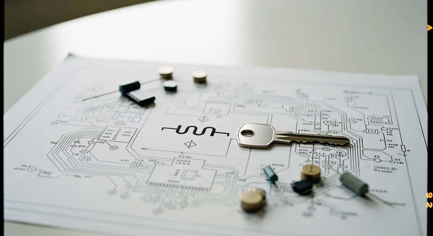
Look at any board layout, and you will find a resistor diagram anchoring the system design. Every electronic circuit requires targeted current control. As a critical circuit component, a resistor provides precise electrical resistance to protect delicate silicon from overcurrent. You rely on these units for dividing voltages and biasing active integrated circuits.
| Benchmark | Market Value |
|---|---|
| 2025 Market Size | $10.67 Billion |
| 2035 Projection | $16.28 Billion |
This essential resistor dynamic drives global manufacturing growth. Reading these prints empowers you to bridge raw hardware with complete system comprehension effortlessly.
Key Takeaways
- Standard schematic symbols help technicians read circuit designs worldwide without language barriers.
- Resistors control current flow and divide voltages to keep delicate microchip pins safe.
- Correct resistor choices protect hardware from extreme heat and prevent dangerous system failures.
- Desoldering one resistor leg isolates the part and yields accurate measurement results during repairs.
Deciphering the Resistor Diagram in Circuit Architecture

Modern integrated circuit designs require clear system integration blueprints. You read a modern resistor diagram to understand entire IC chip solutions and board systems. Companies like Nova Technology Company (HK) Limited, a HiSilicon-designated solutions partner, rely on detailed schematic prints to deploy advanced semiconductor hardware. System integration relies on clean circuit drawings to connect custom silicon with peripheral devices. Every resistor diagram gives engineers clear instructions for managing current across microchips.
Universal Symbols for Global Design Consistency
Standardized schematic symbols allow technicians across the globe to read complex hardware prints instantly. International standard organizations maintain these symbols to clear up confusion across borders. Standardized drawings feature the official resistor circuit symbol so you can recognize passive parts quickly.
The International Electrotechnical Commission manages global standards through detailed published databases:
- Organization Name: International Electrotechnical Commission (IEC)
- Primary Standard: IEC 60617 (Graphical Symbols for Diagrams)
- Scope & Adoption: Global reach, widely utilized across Europe (as EN 60617) and Asia, providing standardized graphical symbols for global compatibility in electrical engineering.
Global committees publish updated resistor schematic symbols to align design rules across industries:
| Standard | Governing Body | Description / Key Details |
|---|---|---|
| IEC 60617 | International Electrotechnical Commission (IEC) | A major global standard containing a database of over 1,750 consistent schematic symbols, originally derived from BS 3939. |
| ANSI Y32 | American National Standards Institute (ANSI) | Provides specialized symbols (initially for aviation) adjusted to align closely with IEC standards. |
| Standard | Implementation / Regional Adaptation | Status / Focus |
|---|---|---|
| IEC 60617 DB | Adopted locally (e.g., NF EN 60617 in France, DIN EN 60617 in Germany) | Current primary international standard for electronic symbols. |
| IEEE/ANSI 315 | Also known as ANSI Y32.2-1975 or CSA Z99-1975 | Inactivated without replacement in November 2019. |
| IEEE/ANSI 91/91a | Revision of ANSI Y32.2 | Inactivated in 2019; defined logic function symbols for digital circuits. |
| AS/NZS 1102 | Australia/New Zealand (modified from IEC 60617) | Withdrawn; users are advised to refer directly to IEC 60617. |
| JIC Symbols | Approved by NMTBA (Specification EGPl-1967) | Historical standard originating from the Joint Industrial Council. |
| IEC 61131-3 | International Electrotechnical Commission (IEC) | Standard specifically governing ladder-logic symbols. |
You locate each resistor on the schematic print without language barriers. You measure line resistance across traces to check signal performance. This design shows how parts limit electrical resistance across complex chips.
Mapping Current Paths and Voltage Division
Schematic prints show passive functions inside system architecture. Every board circuit requires controlled energy to protect active integrated elements. A passive resistor drops excess power before signals enter chip pins. Connecting resistors in series divides voltage steps across sequential nodes. Wiring resistors in parallel reduces voltage drops across separate branches.
A basic voltage divider scales input signals to safe levels. You build a voltage divider with two passives to lower node potential.
- Fundamental Component Equations (Ohm's Law):
- Voltage across first resistor: $V_1 = I_1 \times R_1$
- Voltage across second resistor: $V_2 = I_2 \times R_2$
- Total circuit voltage: $V_{\text{battery}} = I_{\text{total}} \times R_{\text{total}}$
- Series Circuit Rules:
- Total resistance for series connection: $R_{\text{total}} = R_1 + R_2$
- Equal current throughout: $I_{\text{total}} = I_1 = I_2$
- Deriving the Standard Voltage Divider Formula:
- Express current via output voltage: $I_2 = \frac{V_2}{R_2}$
- Express current via total input voltage: $I_{\text{total}} = \frac{V_{\text{battery}}}{R_1 + R_2}$
- Equate currents ($I_2 = I_{\text{total}}$): $\frac{V_2}{R_2} = \frac{V_{\text{battery}}}{R_1 + R_2}$
- Rearrange for output voltage: $V_2 = V_{\text{battery}} \times \frac{R_2}{R_1 + R_2}$
- Deriving the Resistor Ratio Formula:
- Voltage ratio: $\frac{V_2}{V_{\text{battery}}} = \frac{R_2}{R_1 + R_2}$
- Reciprocal ratio: $\frac{V_{\text{battery}}}{V_2} = \frac{R_1 + R_2}{R_2} = \frac{R_1}{R_2} + 1$
- Target resistance ratio equation: $\frac{R_1}{R_2} = \left(\frac{V_{\text{battery}}}{V_2}\right) - 1$
To calculate dropping a 9V source down to a 5V output ($V_2$), substitute the voltage values into the ratio formula: $\frac{R_1}{R_2} = \left(\frac{9}{5}\right) - 1 = 0.8$. Any pair of parts maintaining a ratio of 0.8 will generate the target output voltage. You calculate total resistance by adding components along the main line. You adjust each voltage value for logic chips carefully. Choosing a correct resistor value maintains correct voltage levels across hardware. This calculation provides a helpful ratio value for system designers. You arrange resistors in series to reduce current flow. Placing resistors in parallel lowers total heat. Adding branches alters the total resistance in parallel setups. High total resistance prevents short circuits during continuous operation.
Digital pins need a stable circuit reference when switches remain open. Pull-up and pull-down resistors establish a clear circuit path to a controlled voltage reference whenever a switch remains open. By maintaining this connection, they resolve floating electrical states and apply Kirchhoff's laws to fix the node at a predictable high or low voltage logic level.
| Resistor Type | Switch State | Voltage Level at Input Pin | Resulting Logic Level |
|---|---|---|---|
| Pull-up | Open | Connected to $V_{CC}$ via high-value resistor | Defined HIGH ("1") |
| Pull-up | Closed | Connected directly to Ground (0V) | Defined LOW ("0") |
| Pull-down | Open | Connected to Ground (0V) via low-value resistor | Defined LOW ("0") |
| Pull-down | Closed | Connected directly to $V_{CC}$ | Defined HIGH ("1") |
The input node requires high resistance to save power. You analyze each resistor circuit to verify signal levels. The pull-up resistor pulls open nodes high to stabilize sensitive inputs. Every integrated resistor stabilizes silicon pins during startup. Advanced chip designs feature many resistor applications. Other example resistor applications include pull-up nodes and transmission line terminators. Modern applications require clean signals without noise.
High-frequency transmission lines need proper termination to maintain signal integrity:
| Termination Method | Mechanism / Formula | Functional Role & Signal Impact |
|---|---|---|
| Parallel Termination | Terminated at characteristic impedance (e.g., 50 ohms) | Absorbs all incoming energy at the receiver, preventing signal reflections back toward the driver. |
| Series Termination | Combines with driver output impedance ($Z_{st} = Z_o - Z_{out}$) | Matches total source impedance to line impedance, absorbing reflections returning to the source end. |
- Power Dissipation: Receiver-end termination dissipates incoming signal energy to prevent reflections from bouncing back down the line.
- Signal Integrity: Maintaining impedance matching at the load ensures the pulse keeps sufficient amplitude above noise levels and avoids reflection interference, allowing accurate signal detection.
Place a resistor near the line driver to absorb reflected energy. This resistor absorbs reflection energy cleanly. Standard resistance controls line reflections on high-speed buses. You pick a precise value for pull-down nodes. Select a matching value for signal lines. High speed signals demand a specific impedance value. Current flows through the main circuit smoothly when you match transmission impedances. A series resistor balances input power across fast data channels.
How a Resistor Protects and Controls Power Feed

Power feed distribution networks inside modern microchips require precise current control. You rely on power management circuits to deliver stable energy to sensitive semiconductor silicon. A resistor converts excessive electrical energy directly into safe heat. Every physical component features a strict limit for safe heat dissipation. You must evaluate peak circuit currents and verify component power thresholds. Operating parts above designated electrical ratings introduces severe fire hazards and system failure.
Regulating Current to Protect Delicate Components
Power overload events can damage unshielded components instantly. Overloading specific parts drives internal temperatures far past safe limits. Extreme overheating triggers a self-reinforcing thermal chain reaction inside the unit. This rapid thermal runaway destroys hardware quickly. You manage power safety by evaluating thermal hazards and applying target protection methods:
| Circuit Condition | Thermal & Safety Hazard | Mitigation Strategy |
|---|---|---|
| Average power > Power rating | Permanent resistance alteration, PCB charring, or fire hazard | Select flameproof resistors or use higher rated dissipation |
| Poor air circulation / High ambient temp | Excessive heat accumulation leading to component ignition | Apply power derating and integrate physical heat sinks |
You can protect optoelectronic devices like light-emitting diodes by calculating exact current limits:
- Determine the voltage drop ($V$): Subtract the forward voltage of the diode from the power supply voltage (e.g., $V = 0.3\text{V}$).
- Identify the desired forward current ($I$): Convert the target current into Amperes (e.g., $0.02\text{A}$).
- Apply Ohm's Law ($R = \frac{V}{I}$): Divide the voltage drop by the target current to find the ideal resistance value.
- Calculate the Resistance ($R$): For example, $\frac{0.3\text{V}}{0.02\text{A}} = 15\ \Omega$.
Power Safety Tip: Always select a standard resistance value that equals or exceeds your calculated target value. Higher electrical resistance lowers total heat generation across delicate driver nodes.
Specialized components protect main power rails during extreme system faults:
| Protection Mechanism | How It Operates to Prevent Failure |
|---|---|
| Fault Current Limiting | Uses specific resistance values (e.g., 10–20 ohms) to restrict extreme current spikes during severe system failures while maintaining steady-state operation. |
| Inrush & Transient Management | Absorbs brief surge currents and temporary overvoltage events without tripping, avoiding unnecessary system shutdowns. |
| Definitive Circuit Fusing | Acts as a single-point failure device by permanently opening the circuit when a persistent downstream fault occurs, immediately isolating the power source. |
| Flameproof Safety Coating | Employs specialized external material construction to prevent fire hazards or thermal destruction when the component fuses under extreme heat. |
Resistor Symbols as Universal Energy Consumers
Schematic drawings use standard symbols to represent active electrical loads across diverse industrial applications. Engineers utilize these universal icons to show total power draw along primary supply lines.
- Heat Dissipation Function: Resistors regulate current flow by converting surplus electrical power into thermal energy.
- Maximum Rating Boundary: Every resistor has a designated safe operating threshold for power dissipation. Exceeding this limit leads to rapid overheating, smoking, and destruction of the circuit.
+5V Power Rail ───[ Resistor ]───► Downstream Load (Integrated Circuit)
You calculate total resistance across parallel sub-circuits to determine overall system current demand. Adding parallel branches reduces the total resistance seen by the power supply. A simple resistor circuit shows how energy flows into each functional load block. You balance every component value carefully to prevent power supply overload. You must check each component value on the schematic print to verify system performance before assembly.
Essential Diagnostic Role in Circuit Repairs
Schematic prints guide you through complex board repairs. You trace signal lines to isolate hardware faults in advanced system integration applications.
Tracing Signal Paths for Accurate Failure Analysis
A detailed schematic print shows precise test locations for system diagnosis. Technicians follow a simple process to check a faulty resistor circuit:
- Identify Critical Test Points: Locate marked test nodes on the print, such as TP1 or TP2.
- Perform Parameter Testing: Connect your meter ground lead to the chassis ground. Measure the voltage value at each test node directly.
- Compare Measured Values to Reference Standards: Compare your measured reading against the expected voltage reading listed on the drawing.
- Isolate Circuit Faults Methodically: Trace signal paths step by step to find broken parts or shorted traces.
Oscilloscopes help you diagnose high-speed data channels. A damaged termination resistor distorts clean digital pulses. You will see ringing, overshoot, and undershoot on signal edges. Finding these distorted waveforms helps you replace the damaged part quickly.
Isolating Component Failures During Troubleshooting
You must test individual parts carefully to confirm a hardware failure. Measuring in-circuit components directly often yields an incorrect resistance value:
- Parallel Circuit Paths: Surrounding components form extra current paths. These parallel branches lower your measured resistance below the true value.
- Human Body Contact: Touching probe tips introduces your skin as an extra parallel path. This contact reduces the displayed value even further.
Diagnostic Tip: Desolder one terminal of the resistor from the board before taking a measurement. Isolating the component removes parallel branches and reveals the actual resistance value.
Unsoldering one leg breaks the complete circuit loop. You can now measure the precise resistance without interference. Comparing this result to the schematic print proves whether your resistor works properly.
A complete resistor diagram serves as your essential blueprint for advanced microchip system integration. You master any circuit design faster by learning how each resistor manages electrical power and precise resistance values. These schematic prints fulfill a vital triple purpose:
💡 Core Value:
- Providing a universal engineering language across global design teams.
- Protecting active silicon components against overcurrent conditions.
- Accelerating precise fault isolation during hardware troubleshooting.
Master reading schematic prints today to elevate your practical hardware diagnostic skills!
FAQ
How do you decipher schematic prints on a circuit board?
A resistor diagram shows electrical connections across a board layout. You locate the standardized symbol first. Next, you read the assigned value printed nearby. You can also inspect the physical resistor color code to confirm part specifications.
How do current paths change when wiring components sequentially?
Connecting resistors in series creates a single current path through sequential nodes. You calculate total resistance by adding every component along the line. This configuration scales down current and helps build a basic voltage divider for logic signals.
Why do engineers place resistors in parallel in power management circuits?
You place resistors in parallel to split high electrical current across separate branches. This arrangement lowers overall thermal stress and reduces total resistance. Integrators choose a low component value to maintain high operating efficiency across microchip boards.
How does a voltage divider safeguard delicate microchip pins?
A voltage divider lowers input potential to match safe integrated circuit limits. Wiring resistors in parallel helps establish a target value for signal lines. This simple circuit provides a stable voltage value and precise reference value to protect silicon pins.