5 Simple Steps How to Check for Continuity With a Digital Multimeter
Continuity is a test for a complete, unbroken electrical path. Learning how to check for continuity with a digital
Continuity is a test for a complete, unbroken electrical path. Learning how to check for continuity with a digital multimeter is a fundamental DIY skill. Faulty wiring contributes to an estimated 51,000 home fires annually, so this simple check with a multimeter is crucial for safety. Our team at Nova Technology Company (HK) Limited, a HiSilicon-designated solutions partner, wants you to master continuity testing.
💡 The Simple Answer: A continuous beep from your digital multimeter means the path is good. Silence means the path is broken or "open."
Key Takeaways
- Always turn off power before testing. This protects you and your tools.
- Set your multimeter to continuity mode. This mode often has a sound wave symbol.
- Test your multimeter first. Touch the probes together; it should beep and show low resistance.
- Place probes on each end of the path you want to check. A beep means the path is good.
- No beep or 'OL' means the path is broken. This helps you find problems.
Step 1: Power Off for Safety
This is the most important step. Before you do anything else, you must ensure the circuit or component you are testing is completely de-energized. Your safety, the integrity of your digital multimeter, and the component itself all depend on it.
The Critical Safety Rule
The first rule of continuity testing is simple: never test a live circuit. Your multimeter works by sending its own small electrical current through the component to check for a complete path. If you test a circuit that is already powered, you are essentially connecting two power sources. This action can damage the meter's sensitive internal fuses, destroy the electronic component, or cause a dangerous short circuit, putting you at risk of electrical shock.
💡 Safety First: Professional standards from organizations like OSHA and the NFPA (National Fire Protection Association) mandate that workers must de-energize electrical parts before performing maintenance. This rule is not just for professionals; it is a critical safety practice for everyone.
How to De-energize a Circuit
Making a circuit safe involves more than just flipping a switch. You must remove all potential sources of power.
- Unplug the Device: For appliances and electronics, unplug the power cord from the wall outlet.
- Remove Batteries: If the device is battery-operated, take the batteries out.
- Turn Off the Breaker: For hardwired systems like light fixtures or outlets, go to your electrical panel and switch the corresponding circuit breaker to the "OFF" position.
Be aware that some electronic devices, especially those with power supplies like microwaves or TVs, use capacitors to store high-voltage electrical energy. These components can hold a dangerous charge long after you unplug the device. For these situations, you must safely discharge the capacitors using a proper discharge tool or a high-wattage resistor before you begin testing. After any discharge attempt, always use your digital multimeter in voltage mode to confirm the component's voltage is at or near zero volts before proceeding.
Step 2: Set Up Your Digital Multimeter

With the power off, your next move is to prepare your digital multimeter. A correct setup ensures your test will be both accurate and safe. This involves plugging in the test leads and selecting the right function on the dial.
Plug in the Probes
Your digital multimeter has several ports, or jacks, for the test leads. You must use the correct ones for a continuity test.
- Insert the black test lead into the jack labeled "COM" (which stands for Common).
- Insert the red test lead into the jack labeled with "VΩmA". This port is used for measuring voltage (V), resistance (Ω), and milliamps (mA).
⚠️ Warning: Use the Correct Jacks
Plugging your test leads into the wrong jacks can lead to serious problems. Using the current jacks (often labeled "10A") for a non-current test can cause:
- Inaccurate or zero readings.
- Blowing the internal fuse of the meter.
- Damage to the circuit you are testing.
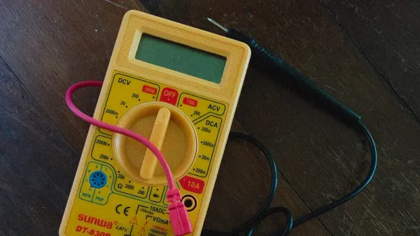
Select the Continuity Mode
Now, you need to tell your meter what you want to measure. Turn the large rotary dial on your digital multimeter to the continuity mode setting. This function is usually marked with a symbol that looks like a sound wave or a series of parallel arcs: 🔊 or •))). On many models, this setting shares a spot on the dial with the resistance (Ω) or diode test mode. You may need to press a "function" or "select" button to switch to the continuity test mode.
When you handle your meter, you might notice safety ratings like "CAT II" or "CAT III" printed on it. These are important safety standards.
| CAT Rating | Common Uses |
|---|---|
| CAT I | Protected electronics not connected to wall power. |
| CAT II | Household appliances and tools plugged into wall outlets. |
| CAT III | Building wiring, circuit breakers, and distribution panels. |
| CAT IV | The source of power, like outdoor power lines. |
For most DIY projects around the house, a CAT II or CAT III rated meter is appropriate. Selecting the continuity mode prepares the meter to send a small current through the test leads to check for a complete path.
Step 3: Test the Meter's Operation
Before you test your component, you need to test your tool. This quick check confirms that your digital multimeter, its batteries, the test leads, and the internal fuse are all working correctly. Skipping this step can lead you to believe a good part is faulty, wasting time and money.
How to Verify the Setup
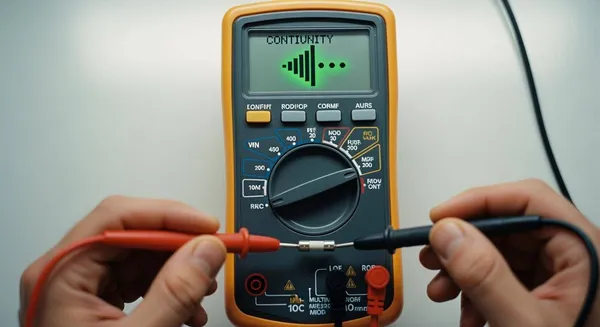
Verifying your setup is the easiest part of the whole process. With the meter on and in continuity mode, simply touch the metal tips of the red and black probes firmly together. This simple action creates a short circuit, which is exactly what you want for this test. You are creating a perfect, complete path for the meter's own current to flow from one probe to the other.
Confirming the Beep and Reading
When you touch the probes together, you should get immediate feedback.
- A clear, continuous beep: The sound tells you the circuit is complete.
- A low resistance reading on the screen: This confirms the quality of the connection.
💡 What to Expect on the Display Ideally, the screen should show a resistance of 0 Ω. However, your test leads have their own small amount of resistance. A real-world reading between 0.2 Ω and 0.5 Ω is perfectly normal and indicates a good setup.
If you touch the probes together and hear silence, your setup has a problem. Check that your leads are plugged into the correct jacks and that you have selected the continuity mode. If everything looks right but you still get no beep, the meter's internal fuse may be the issue. A digital multimeter with a blown fuse will not beep; instead, the display will likely show 'OL' (Open Line), indicating a break in the circuit inside the meter itself.
Step 4: How to Test Continuity with a Multimeter
You have confirmed your digital multimeter works. Now you are ready for the main event: testing your component. Proper technique here is key to getting an accurate result. This step shows you how to check for continuity with a digital multimeter by placing the probes correctly and ensuring a solid connection.
Probe Placement on a Component
The basic idea is to touch one probe to each end of the electrical path you want to check. The meter will send a small current out of one probe, through the component, and back into the other probe.
Your approach will change slightly depending on what you are testing.
- For Wires or Fuses: Place one probe on each end. The order of the red and black probes does not matter.
- For Switches: Place one probe on the input terminal and the other on the output terminal. You will need to test the switch in both its "on" and "off" positions.
- For Diodes: Diodes only allow current to flow in one direction. Place the red probe on the anode and the black probe on the cathode (the end usually marked with a stripe). A good diode will beep in this direction but not when you reverse the probes.
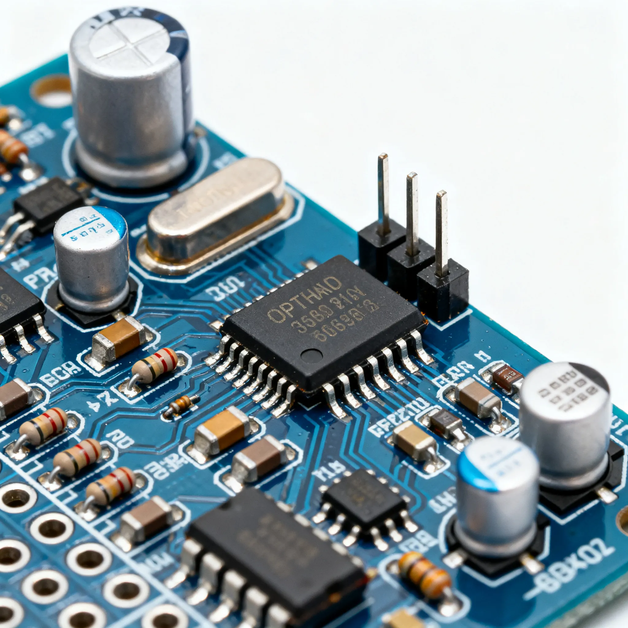
⚠️ Important Note on Complex Parts You should not use a basic digital multimeter for testing components like microprocessors or memory chips. These integrated circuits (ICs) are too complex and require specialized equipment like a logic analyzer.
Getting a Good Connection
A poor connection can give you a false result. Dirt, paint, rust, or surface oxidation can prevent the meter's current from flowing. This can make a good wire seem broken.
- Press Firmly: Make sure the metal tips of your probes make solid contact with the metal of the component.
- Clean the Contact Points: If a surface looks dirty or corroded, you may need to clean it with a wire brush or sandpaper.
- Be Patient: Hold the probes steady until the reading on the screen stabilizes. Rushing can lead to inaccurate results.
When you test continuity with a multimeter, you need a clean, metal-to-metal connection. Sometimes, a thin, invisible layer of oxidation can block the connection. You can often break through this layer by pressing the probe tips firmly or gently scratching the surface. This is a vital part of how to check for continuity with a digital multimeter correctly.
Step 5: Interpret the Test Results
You have completed the test. Now you need to understand what your digital multimeter is telling you. The results are straightforward and will give you a clear "yes" or "no" answer about the electrical path. Interpreting the sound and the screen reading is the final piece of the puzzle.
Beep and Low Resistance: Good Continuity
A clear, continuous beep is the most obvious sign of good continuity. This sound tells you that the meter's current has successfully traveled from one probe to the other, confirming a complete and unbroken path.
Along with the beep, you should look at the display. It will show a very low resistance value, usually close to zero ohms (Ω). You will likely not see exactly 0.0 Ω. This is normal. Even the best connections have a tiny amount of resistance.
💡 Why Isn't the Reading Exactly Zero?
A perfect reading of 0.0 Ω is rare in the real world. Your reading will be slightly higher because:
- Your test leads themselves have a small amount of internal resistance.
- Manufacturing standards, like EN 60115-2, allow for tiny variations. Even components designed to have zero resistance can have a maximum resistance of 10 to 50 milliohms (0.01 to 0.05 Ω).
A reading between 0.2 Ω and 1.0 Ω is excellent and confirms you have a solid, continuous circuit.
No Beep and 'OL': An Open Circuit
If you hear silence when you touch the probes to your component, it means there is no continuity. The electrical path is broken. This is known as an "open circuit" or "open line."
To confirm this, look at the meter's screen. It will likely display 'OL'.
What does 'OL' mean?
'OL' stands for "Over Limit" or "Open Loop." It means the resistance of the component you are testing is too high for the meter to measure. In a continuity test, this effectively means the resistance is infinite, confirming a complete break in the circuit.
If you get an 'OL' reading, you have found the problem. The wire is broken, the fuse is blown, or the switch is faulty. You can now confidently move on to replacing the bad component.
Common Continuity Testing Applications
Now that you know the steps, you can apply this skill to many real-world problems. This simple test is a powerful tool for diagnosing issues in electronics and electrical systems.
Checking Wires and Cables
Wires can break internally even when the outer insulation looks fine. Mechanical damage from stress or vibration often causes these hidden breaks. You can easily perform testing a wire for these faults.
- Place one probe on each end of the wire.
- A beep confirms the wire is good.
- Silence means you have an open circuit, and the wire needs replacement.
For complex cables like USB or Ethernet, you can test each individual pin. However, professionals often use a specialized cable tester to quickly verify all connections at once.
Testing Fuses and Breakers
Fuses are designed to be a weak link that breaks to protect a circuit. Testing a fuse is a common and easy check. Remove the fuse from the device and place a probe on each of its metal ends.
- Good Fuse: Your meter will beep, showing a complete path.
- Blown Fuse: You will hear silence and see 'OL' on the screen.
This same logic applies to circuit breakers. After turning off the main power, you can perform a similar test on a breaker removed from the panel. Proper continuity testing helps you quickly identify a blown fuse.
Verifying Switches
Switches can fail by getting stuck open or closed. The process of testing switches helps you find these faults. With the switch in the "ON" position, place your probes on the input and output terminals. You should hear a beep. Then, flip the switch to the "OFF" position. The beep should stop. If it beeps in both positions, the switch is stuck closed. If it never beeps, it is stuck open. For a multi-position switch, like a fan speed selector, you repeat this process for each setting to ensure every connection works correctly. Inconsistent or high resistance readings are clear signs that you need to replace the switch.
Inspecting Solder Joints
On a printed circuit board (PCB), a bad solder joint can cause a device to fail. These defects, like a "cold joint" where the solder did not melt correctly, create high resistance. A good solder joint should have a resistance reading below 0.1 ohms.
💡 Professional Application At companies like Nova Technology Company (HK) Limited, a HiSilicon-designated solutions partner, technicians use these precise checks to validate connections on complex circuit boards.
If you test a solder joint and get a high resistance reading or no beep at all, you have likely found a cracked or cold joint that needs to be repaired.
You now know how to check for continuity with a digital multimeter. This simple test is a powerful troubleshooting skill. Remember the core lesson:
💡 Beep = Good Path | Silence = Broken Path
Mastering how to check for continuity with a digital multimeter just takes practice. You can confidently diagnose issues by following these five steps:
- Power Off for Safety
- Set Up Your Meter
- Test the Meter
- Test the Component
- Interpret the Results
This knowledge empowers you to find and fix electrical faults in many projects.
FAQ
What if my meter beeps but shows high resistance?
A beep with a high resistance reading signals a problem. You likely have a poor connection or a failing component. A good, continuous path should always show a resistance value very close to zero ohms (Ω).
Can I test continuity on a circuit board?
Yes, you can test components on a circuit board. You must first remove all power from the board. You should also try to isolate the component you are testing to get an accurate reading without interference from other parts.
Why doesn't probe color matter for continuity?
The order of the red and black probes does not matter for a simple continuity test. The test just sends a current to check for a complete path. It does not measure polarity, so either probe can complete the circuit.
What does 'OL' mean on my multimeter? 🧐
The 'OL' symbol on your screen is a very important message.
'OL' stands for "Over Limit" or "Open Loop." It tells you the resistance is too high to measure. This means you have found a break, or an "open," in the electrical path.