Continuity Explained for Beginners in Electronics
When you ask, "continuity what does it mean" in electronics, you look for an unbroken path that lets ele
When you ask, "continuity what does it mean" in electronics, you look for an unbroken path that lets electric current flow. Imagine water flowing through a pipe. If you cut the pipe and cap the ends, water stops moving—just like electrons stop when a wire breaks. In electronics, continuity means you have a complete path for electricity, much like a solid pipe keeps water moving. You need to understand continuity to check if wires, switches, or circuits work as expected.
Many beginners confuse how components behave in a circuit. For example, some think capacitors store current or that all inductors are the same. See the table below for common misconceptions:
| Misconception | Explanation |
|---|---|
| Inductors need a continuity path for current | You need a diode to keep current flowing when a switch opens. |
| All capacitors and inductors are the same | Different types behave differently in circuits. |
| Capacitors store current | Capacitors store energy, not current. |
Key Takeaways
- Continuity means having a complete path for electric current to flow. Without it, devices won't work.
- Use a multimeter to test for continuity. A beep or low resistance indicates a good connection.
- Regular continuity testing helps prevent electrical issues, such as blown fuses and faulty switches.
- Always turn off power before testing to ensure safety and protect your equipment.
- Practice testing often to build your skills and confidence in working with electronics.
Continuity What Does It Mean
Definition of Continuity
When you work with electronics, you often hear the question: continuity what does it mean? In simple terms, continuity means you have a complete path for electric current to flow. If you picture a wire connecting a battery to a light bulb, continuity exists when the wire is unbroken and the bulb lights up. Industry standards define continuity as a closed circuit that allows current to move from one point to another without interruption. You use continuity testing to check if a circuit works as it should. If the path is complete, electricity flows, and the device operates correctly.
Open vs Closed Circuit
You need to understand the difference between open and closed circuits to answer continuity what does it mean. An open circuit has a break or gap, so current cannot flow. A closed circuit forms a loop, letting current move freely. The table below shows the main differences:
| Basis of Difference | Open Circuit | Closed Circuit |
|---|---|---|
| Definition | An electric circuit in which there is a gap or break and disallows the flow of current is called an open circuit. | An electric circuit which has a closed loop through which current can flow is called a closed circuit. |
| State of circuit | Open circuit represents the OFF state of the circuit. | Closed circuit represents the ON state of the circuit. |
| Path | An open circuit is a discontinuous path. | A closed circuit is continuous path. |
| Continuity | There is no continuity in the open circuit. | The closed circuit has continuity. |
| Electric current | In open circuit, the electric current cannot flow in the circuit, i.e. current is zero. | A definite current flows in the closed circuit. |
| Voltage | In an open circuit, the entire supply voltage appears across the open terminals of the circuit. | In a closed circuit, the supply voltage is distributed across the loads depending on the load parameters. |
| Circuit resistance | The resistance of an open circuit is ideally infinite, but practically very high. | The resistance of the closed circuit is relatively less than open circuit and is decided by the circuit elements such as resistance of wires, elements, etc. |
| Examples | A common example of an open circuit is the circuit of a lamp with the switch in the OFF state. | The example of a closed circuit is the circuit of a lamp with the switch in the ON state. |
When you test a circuit, you look for continuity to confirm that the path is closed and ready for current.
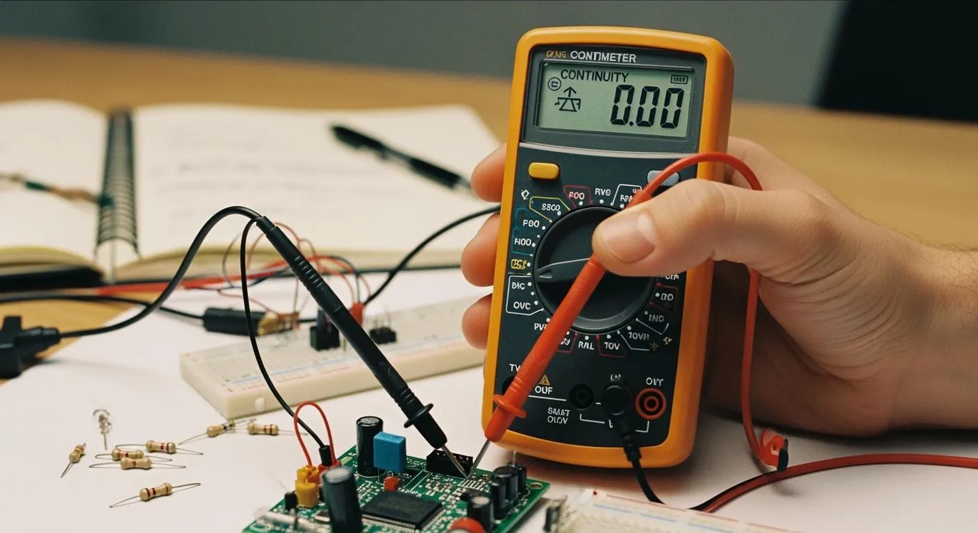
Continuity and Resistance
You can use resistance to check for continuity. When you measure resistance between two points in a circuit, low resistance means you have continuity. High resistance means the path is broken, so there is no continuity. Most digital multimeters show a beep or a low number when you have continuity. Here is what the resistance values usually mean:
- A reading of less than 1.0 ohms means excellent conductivity.
- Values between 0 and 50 ohms usually indicate continuity.
- Higher values, like 86.7 ohms or 1599 ohms, show moderate continuity.
- Values above 2.2 megaohms (MΩ) mean there is no continuity.
If you want to know continuity what does it mean in practical terms, remember: low resistance equals a good path for current, and high resistance means the path is blocked. You use this knowledge to find broken wires, faulty switches, or damaged circuit traces. Understanding continuity helps you keep your electronic projects working and safe.
Why Continuity Matters
Nova Technology Company (HK) Limited stands as a HiSilicon-designated solutions partner. The company specializes in chip-level solutions and system integration for advanced electronics. You will find their expertise in integrated circuit design, embedded systems, and applications such as smart surveillance, IoT devices, and multimedia processing.
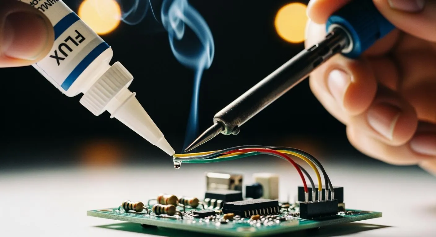
Checking Connections
You need to check connections in every electronic project. Continuity testing helps you confirm that wires, switches, and fuses work as intended. If you want to make sure your electrical circuit operates without interruption, you should use a multimeter to test for continuity. This process lets you find broken wires, faulty switches, or blown fuses before they cause bigger problems.
- Continuity testing confirms that electrical circuits are unbroken, which is vital for the functionality of wires, switches, and fuses.
- You use a multimeter to check for complete connections, ensuring that components are operational without interruptions.
- When you test a fuse, a beep from the multimeter means the fuse works. No sound and a high resistance reading mean the fuse is faulty.
You should also follow best practices when checking connections. The table below shows some important steps:
| Best Practice | Description |
|---|---|
| Visual Inspection | Look for broken traces, loose wires, or burned components. |
| Verify the Power Supply | Measure voltage at input points to ensure proper levels. |
| Test Individual Components | Use a multimeter to check resistors, capacitors, diodes, and transistors. |
| Inspect and Repair Connections | Make sure all solder joints and connectors are secure and working. |
Preventing Electrical Issues
You can prevent many electrical problems by testing for continuity. This method helps you find open circuit faults, which often cause inconsistent power or blown fuses. The table below lists common issues you can avoid:
| Evidence Description | Source |
|---|---|
| Continuity testing is used to troubleshoot open circuit faults, which are common electrical issues. | Troubleshooting: Continuity Testing 340 |
| Identifying open circuit faults helps prevent inconsistent electrical supply and blown fuses. | TIP: CHECK SWITCHES AND CONTACTORS FOR CONTINUITY |
| Faulty switches and contactors can lead to equipment damage, which continuity testing can help prevent. | Mastering Continuity Testing: The Ultimate Guide for Electronic Design Engineers |
Continuity testing gives you a simple way to keep your devices safe and reliable. You can avoid system downtime and dangerous situations by making this test part of your regular maintenance routine.
How to Test for Continuity
Tools Needed
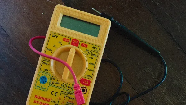
You need the right tools to test for continuity in electronic circuits. The most common tool is a multimeter. You can use either a digital or analog multimeter. Both types can check for viable connections between two points. Multimeters have a continuity mode that helps you trace electrical connections and spot trouble spots, such as short circuits. You can also use a continuity tester. This tool checks if there is a complete electrical pathway and gives a simple pass or fail result. Continuity testers work best when the power is off. Multimeters, on the other hand, can measure voltage, current, and resistance, making them more accurate and versatile for continuity testing.
Common tools for testing for continuity:
- Digital multimeter (with continuity mode)
- Analog multimeter
- Continuity tester
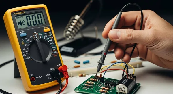
Step-by-Step Test for Continuity
You can follow these steps to test for continuity safely and accurately:
- Turn off the power to the circuit. This step prevents electrical hazards.
- Set your multimeter to continuity mode. Look for a soundwave or audible alarm symbol.
- Touch the probes together to check the meter. You should hear a beep, which means the meter works.
- Place the probes on the two ends of the wire, switch, or component you want to test.
- Listen for a continuous beep or check for a low resistance reading. This result means you have continuity.
- If you hear no beep or see infinite resistance, the path is open and there is no continuity.
- When you finish, turn off the meter and store it safely.
Tip: Always double-check your meter before and after testing for continuity to make sure your results are accurate.
Safety Tips
You must follow safety rules when testing for continuity. Always turn off the power before you start. Never test live circuits unless you have special training. Wear personal protective equipment, such as insulated gloves and safety glasses. Do not work alone in hazardous areas. Make sure your test instrument is rated for the environment. Keep warning signs visible if you must work near live circuits. Avoid working where water could enter the equipment. These steps help you stay safe and prevent accidents during continuity testing.
You now know that continuity means having a complete path for electricity to flow. Testing for continuity helps you find broken wires, faulty switches, and cold solder joints. Regular checks reduce equipment failures and keep your home or workplace safe from shocks and fires.
- Always turn off power before testing.
- Use a multimeter to check connections.
- Practice often to build your skills.
Keep learning and testing. You will gain confidence and protect your electronic projects.
FAQ
What does continuity mean in electronics?
You check for continuity to see if electricity can flow through a wire or circuit. If the path is complete, current moves easily. If there is a break, current stops.
How do you test for continuity?
You use a multimeter or a continuity tester. Turn off the power. Touch the probes to both ends of the wire or component. A beep or low resistance means you have continuity.
Why is the continuity feature important on a multimeter?
You use the continuity feature to quickly find broken wires, faulty switches, or bad connections. This tool helps you fix problems before they cause bigger issues in your circuit.
Can you test continuity with power on?
You should never test continuity with power on. Always turn off the circuit first. This keeps you safe and protects your testing tools from damage.
What does it mean if there is no continuity?
No continuity means the path is broken. Electricity cannot flow. You may have a cut wire, a blown fuse, or a faulty switch.