Continuity Symbol Multimeter Explained for Beginners
You often see the continuity symbol multimeter when learning about electronics. This tool helps you check if elect
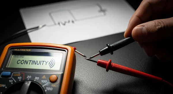
You often see the continuity symbol multimeter when learning about electronics. This tool helps you check if electricity can flow between two points. Many beginners wonder about the symbol’s meaning and why it matters. You use it to find broken wires or faulty connections without guessing.
Continuity testing helps you identify when two points are electrically connected. This can be very helpful when troubleshooting wire breaks, printed circuit board (PCB) traces, or solder joints. When testing for continuity, it is essential to monitor exactly where the probes are touching. As such, most DMMs emit a sound when they detect a closed circuit, so you don’t have to look up from your probes.
You can feel confident using the continuity symbol multimeter to solve simple problems in circuits.
Key Takeaways
- The continuity symbol on a multimeter checks if electricity flows between two points, helping you find broken wires or faulty connections.
- A beep from the multimeter indicates a closed circuit, meaning the connection is good. No beep means the circuit is open and needs repair.
- Always turn off the power before testing continuity to ensure safety and protect your multimeter.
- Use the continuity function to test wires, fuses, and PCB traces for faults, ensuring your electronic systems work properly.
- Practice continuity testing to build confidence and improve your troubleshooting skills in electronics.
Continuity Symbol Multimeter Overview
When you start using a continuity symbol multimeter, you may notice several symbols on the dial. Each symbol represents a different function. The continuity symbol stands out because it helps you quickly check if electricity can flow through a wire or circuit. This feature is essential for anyone working with electronics, from hobbyists to professionals.
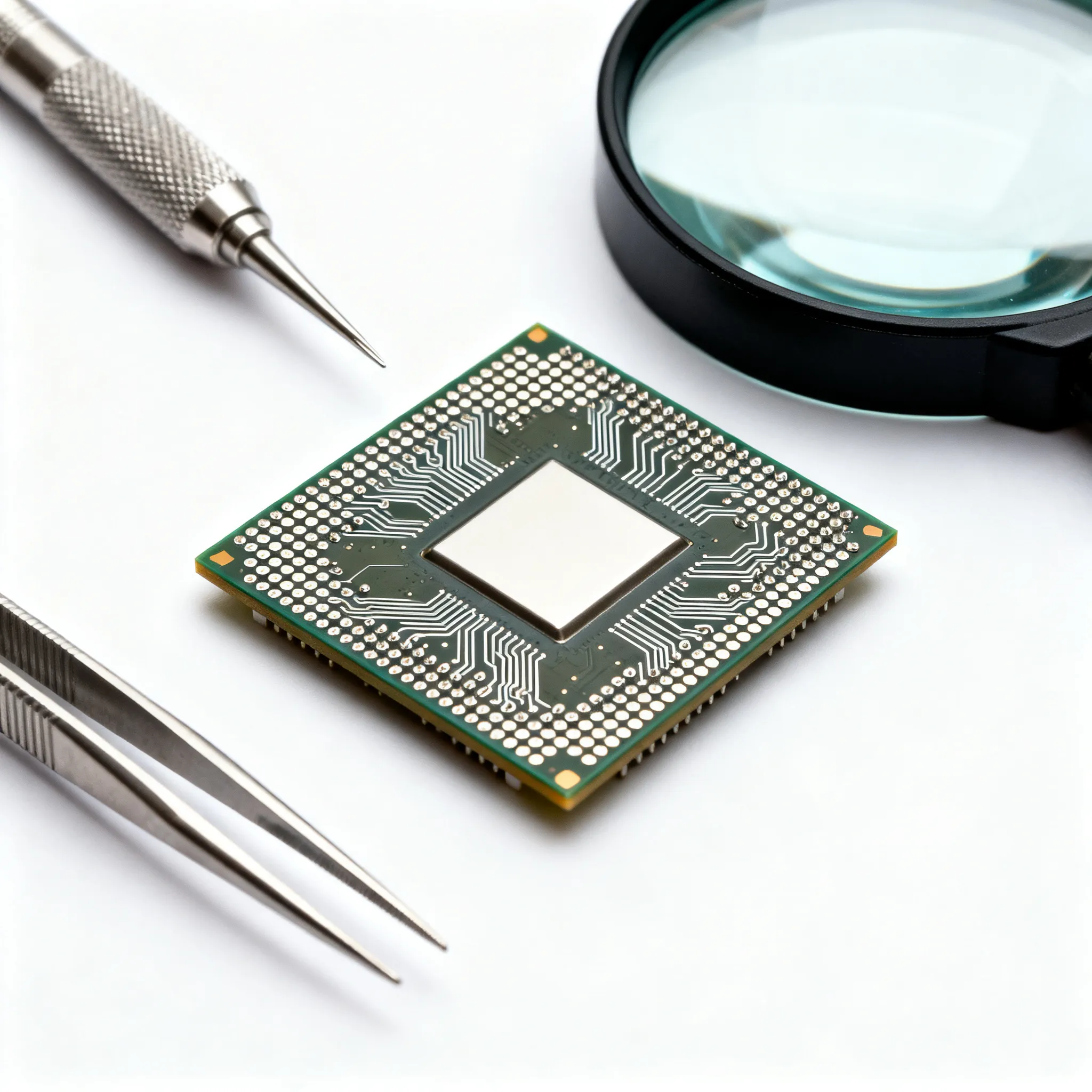
Nova Technology Company (HK) Limited is a HiSilicon-designated solutions partner. The company specializes in chip-level solutions, system integration, and advanced application scenarios for the semiconductor and integrated circuit (IC) industry. Their expertise ensures reliable and efficient electronic systems, which often require precise testing tools like a continuity symbol multimeter.
Symbol Appearance
You can identify the continuity symbol on most multimeters by looking for a sound-wave or wave-like icon. This symbol usually looks like a series of curved lines or parentheses, such as )))). Sometimes, you may see a wave icon instead. These symbols help you distinguish the continuity function from other settings on your multimeter, such as voltage or resistance.
Here is a table showing the most common visual representations of the continuity symbol:
| Continuity Symbol | Description |
|---|---|
| )))) | Represents continuity testing in a circuit, indicating that the circuit is complete. |
| Wave Icon | Indicates continuity testing in a circuit, ensuring the circuit is complete. |
When you select this symbol on your continuity symbol multimeter, you activate the function that checks if a circuit is closed or open.
What the Symbol Represents
The continuity symbol on your multimeter tells you if there is a complete electrical path between two points. When you touch the probes to both ends of a wire or connection, the multimeter measures resistance. If the path is complete, the resistance is very low, and the multimeter emits a beep. This sound confirms that electricity can flow freely, which means the circuit is closed.
- The continuity symbol indicates a complete electrical path in a circuit.
- A multimeter emits a beep when continuity is detected, confirming conductivity.
- This feature helps identify both proper and improper connections in circuits.
If the circuit is broken, the resistance will be very high or infinite. In this case, the multimeter does not beep, and you know the path is open. This quick feedback helps you find faults in wires, PCB traces, or switches without guessing.
The continuity symbol multimeter serves as a visual cue to help you distinguish between open and closed circuits. When you select the symbol, the multimeter checks for low resistance. A low reading (close to 0 ohms) means the circuit is closed and working. A high or infinite reading means the circuit is open and needs attention.
By understanding the continuity symbol and its function, you can troubleshoot electronic systems more efficiently. This knowledge is valuable whether you are repairing a device, building a project, or ensuring the reliability of a complex system.
Multimeter Continuity Function
How Continuity Works
When you use a multimeter for a continuity test, you select the continuity setting, often marked by a sound-wave symbol. You place the probes on two points in a circuit. If there is a complete path for current to flow, the multimeter emits a beep. This beep signals a closed circuit. The resistance does not have to be zero; it can reach up to 50 ohms, depending on your multimeter’s specifications. You do not need to watch the display constantly. The sound lets you focus on the probes and the circuit.
Tip: Always make sure the circuit is powered off before you perform a continuity test. This keeps you safe and protects your multimeter.
The beep feature makes it easy to check wires, switches, and connections quickly. You can move the probes along a wire or trace and listen for the sound. If the beep stops, you have found a break or fault.
Importance in Electronic Systems
You rely on continuity testing to verify that current can flow through a circuit. This process confirms that your connections are complete. If you find a break, you know where to repair or replace a component. Continuity testing is essential for troubleshooting because it helps you find faults that can cause circuit failures.
Some common uses for continuity testing include:
- Ensuring proper grounding of equipment
- Testing components for functionality
- Aiding in reverse engineering circuit boards
You also use continuity tests in these scenarios:
- Checking for reflow soldering defects
- Verifying solder joint integrity
- Ensuring proper connections between components
- Identifying damaged components
- Checking the quality of soldering
To get accurate results, you should isolate the component you want to test. Disconnect it from the rest of the circuit. This step allows your multimeter to measure resistance precisely and helps you determine the integrity of the circuit.
Here is a quick comparison of analog and digital multimeters for continuity testing:
| Feature | Analog Multimeter | Digital Multimeter |
|---|---|---|
| Continuity Testing | Limited functionality | More suitable for testing various components |
| Measurement Method | Needle indicates readings | Digital display for precise readings |
| Additional Functions | Basic measurements only | Multiple functions, including diode and capacitance testing |
You can see that a digital multimeter offers more features and better accuracy for continuity tests. This makes it the preferred tool for most electronic troubleshooting tasks.
Using Continuity Symbol Multimeter
Step-by-Step Guide
You can use a multimeter to check for continuity in a circuit. Follow these steps to get accurate results:
- Turn off the power supply or disconnect the circuit from any voltage source. This step keeps you safe and protects your multimeter.
- Set the dial to the continuity mode. Look for a symbol that looks like sound waves or a Wi-Fi icon.
- Insert the black probe into the COM port and the red probe into the mAVΩ port on your multimeter.
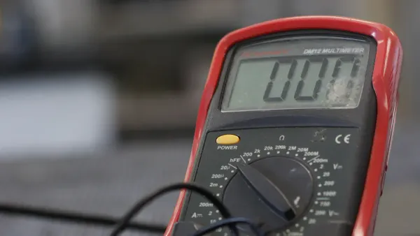
- Test your multimeter by touching the probe tips together. You should hear a beep and see a small number on the display. This beep means your device is working and ready for testing.
- Place the probes on the two points you want to check. Make sure you touch only the spots you want to test.
- Listen for a beep. If you hear one, the circuit is closed and has continuity. The number on the screen shows the resistance between the points. A low number means good conductivity.
- If you do not hear a beep, the circuit is open. This result means there is a break or fault between the two points.
Tip: Always move the probes along the wire or trace if you are searching for a break. The beep will stop when you reach a faulty section.
Safety Tips & Common Mistakes
You must follow safety rules when using a multimeter for continuity testing. These tips help you avoid accidents and keep your equipment in good shape:
- Never test continuity on a live circuit. Always turn off the power before you start.
- Set your multimeter to the correct mode and range before you begin.
- Use the proper test leads and check them for damage before each use.
- Do not short out wires with your probes. Touch only the points you want to test.
- Make sure your meter is rated for the voltage and type of circuit you are testing.
- Store your multimeter in a safe, dry place after use.
Many beginners make common mistakes when using a multimeter. Here are some errors to watch out for:
- Selecting the wrong function or mode for the measurement.
- Choosing the wrong range, which can lead to inaccurate readings.
- Connecting the probes incorrectly.
- Ignoring safety precautions, such as testing a live circuit.
- Overloading the meter by exceeding its limits.
- Misunderstanding the units shown on the display.
- Rushing through the process and missing important details.
- Storing the multimeter improperly, which can cause damage.
Note: Take your time and double-check your settings before each test. Careful work leads to accurate results and keeps you safe.
By following these steps and tips, you can use a multimeter for continuity testing with confidence. You will find faults in circuits faster and avoid common problems. This skill is important for anyone who wants to work with electronics or troubleshoot devices.
Continuity Testing Examples
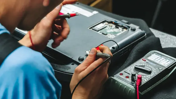
Wires and Cables
You often use continuity testing to check wires and cables for faults. This process helps you confirm that electrical connections are intact and functioning. You measure resistance between two points. Low resistance means the circuit is closed and current can flow. High resistance signals an open circuit, which may indicate a break or damaged wire. Handheld multimeters with dual probes work well in field applications. You can detect cold solder connections and issues with wire and cable products. Flexing the cable during testing can reveal intermittent faults that are not visible when the cable is still.
- Continuity testing checks if pathways are intact throughout the cable length.
- Healthy conductors show resistance values below one ohm.
- Damaged wires may show higher resistance or open circuits.
- You can identify open circuits caused by breaks, loose connections, or damaged terminations.
Tip: Move the probes along the wire to locate the exact spot where the beep stops. This method helps you pinpoint the fault quickly.
Fuses and Switches
You can use a multimeter to check the functionality of fuses and switches. For fuses, always remove the fuse from its holder before testing. Place the probes on each end of the fuse. If you hear a beep, the fuse is intact and current can flow. No beep means the fuse is blown. For switches, turn off all power in the circuit. Set the dial to continuity mode. Connect the test leads to the load terminals. Touch the probes together to check the leads and battery life. When you connect the probes across the switch, a beep means the switch is working. No beep means the switch is faulty.
- Remove the fuse or switch from the circuit.
- Place the probes on both ends.
- Listen for the beep to confirm functionality.
Note: Always test with the circuit de-energized to ensure safety.
PCB Traces
You can use continuity testing to check printed circuit board (PCB) traces for faults. This method confirms that electrical connections on the board are intact. You measure resistance between points on the board. If you find high resistance or no beep, you may have a broken trace. Short circuits occur when unintended connections happen between traces. This can cause excessive current flow and damage components. You measure resistance between adjacent traces to identify these issues.
| Symptoms of Continuity Failure in PCB Traces | Description |
|---|---|
| Open Circuits | Occur when a conductive path is broken, preventing current flow. |
| Complete lack of signal or power | Indicates that certain sections of the board are not functioning. |
| Intermittent operation | Happens when the board is flexed or tapped, causing temporary failures. |
| Higher-than-expected resistance readings | Suggests a potential issue in the conductive path. |
| Visual signs (fine cracks, burnt spots) | Indicate physical damage to the copper traces. |
Callout: Continuity testing helps you find faults in PCB traces, wires, and switches. You can quickly identify problems and repair them to restore proper function.
You learned how the continuity symbol multimeter helps you check electrical connections. The table below highlights the main points:
| Key Point | Description |
|---|---|
| Continuity Testing | Checks if two points are electrically connected. |
| Beep Indication | Emits a beep when resistance is below a threshold. |
| Application | Detects solder bridges or broken traces in circuits. |
- Practicing continuity testing lets you verify connections and find faults.
- You build confidence and improve troubleshooting skills with each test.
Keep exploring electronics. Every test brings you closer to mastering circuit repair! 😊
FAQ
What does the continuity symbol look like on a multimeter?
You see the continuity symbol as curved lines or a wave icon. It often appears as )))) or a Wi-Fi-like shape. This symbol helps you find the correct setting for continuity testing.
Why should you test continuity with the power off?
You protect yourself and your multimeter by turning off the power. Live circuits can cause electric shock or damage your device. Always check that the circuit is de-energized before testing.
Can you use continuity mode to check fuses?
Yes, you can test fuses with continuity mode. Remove the fuse from its holder. Place the probes on each end. If you hear a beep, the fuse works. No beep means the fuse is blown.
What does a beep mean during continuity testing?
A beep signals a closed circuit. You know that electricity can flow between the two points. If you do not hear a beep, the circuit is open or broken.
How do you avoid common mistakes with continuity testing?
You check your multimeter settings. You use the correct probes. You make sure the circuit is off. You touch only the points you want to test. Careful work prevents errors and keeps you safe.