SMDJ70CA Datasheet and Pinout: Specs for Design and Sourcing
SMDJ70CA datasheet essentials, pinout overview, key specs, and design/sourcing checks for engineers and buyers. Request a quote on IC-Online.
Why the SMDJ70CA Matters for Today’s High-Voltage DC Rails and Lead-Time Woes
The move to 24 V and 48 V power architectures in industrial motor drives, server backplanes, Power‑over‑Ethernet (PoE++) and mild‑hybrid 48 V automotive systems has placed bidirectional TVS diodes squarely on the BOM of every power‑supply engineer. A single load dump or cable‑ring transient on a 48 V rail can exceed the absolute maximum ratings of sensitive downstream regulators, making the SMDJ70CA a first‑line defence. Its 70 V standoff voltage sits just above a 48 V bus’s worst‑case charge voltage, giving designers the headroom to pass regulatory immunity tests without adding unnecessary clamping‑diode leakage.
That headroom matters more now than ever. Component supply chains remain fragile: the industry is still navigating allocations that began in 2021, and a 2026 shortage analysis warns that requalification of genuine second sources for transient‑protection devices can take months, not weeks. At the same time, transient‑induced failures continue to trigger safety recalls across consumer and automotive electronics, as visible in alerts from CPSC and NHTSA. For engineers, getting the SMDJ70CA right in the design phase and for procurement, locking a diversifiable supply path are no longer optional priorities—they are critical. Use Octopart to scan active distributor pricing and ready‑to‑ship inventory before you commit the BOM.
Reading the SMDJ70CA Datasheet: Breakdown, Clamping, and Power Handling
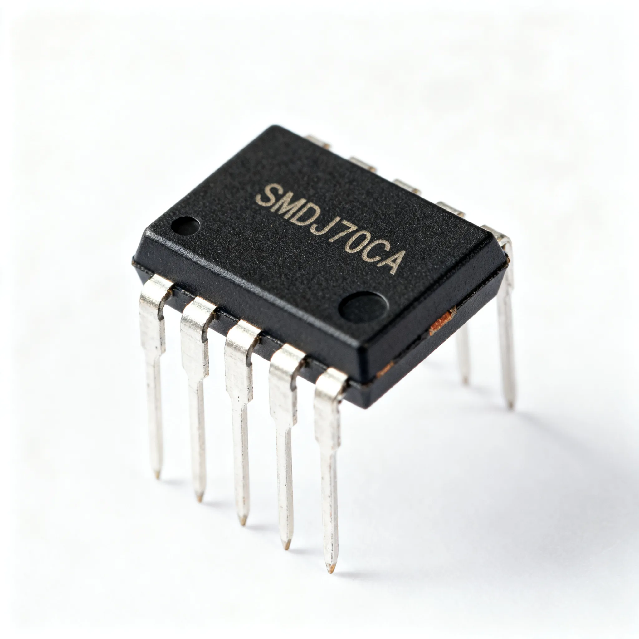
The SMDJ70CA from Littelfuse is a 3000 W peak pulse power, bidirectional transient voltage suppressor housed in the low‑profile SMC (DO‑214AB) package. It is built on a silicon avalanche diode process, designed to absorb the energy of lightning‑induced surges (IEC 61000‑4‑5) and inductive load‑dump transients without latching up. Key electrical parameters are defined by the manufacturer’s datasheet, and cross‑referencing with the Eaton SMDJ series datasheet (2025) and the Littelfuse SMCJ70A data gives a consistent picture of the technology.
Understanding the bidirectional nature of the “CA” suffix is crucial. Unlike the unidirectional SMDJ70CA (which would be marked SMDJ70A), the bidirectional die stacks two identical avalanche junctions in series back‑to‑back. This gives symmetrical clamping in both polarities and eliminates the polarity‑sensitive cathode stripe. In the field, you’ll see no band on the body; the pinout is symmetrical—both terminals are equivalent. For unidirectional SMDJ70A, the cathode connects to the notched side and the anode to the opposite terminal. Mistaking a bidirectional for a unidirectional part on a DC rail that never reverses is usually harmless (the reverse standoff is still 70 V), but using a unidirectional part on an AC‑coupled line will clamp only one half‑cycle, which is a common field‑failure root cause.
The table below consolidates the Tier‑A specs that every design engineer and sourcing manager should have at hand when evaluating the SMDJ70CA.
| Parameter | Value/Range | Unit/Notes |
|---|---|---|
| Part Number | SMDJ70CA | Bidirectional; Littelfuse (other mfrs verify specs) |
| Peak Pulse Power (10/1000 μs) | 3000 | W |
| Standoff Voltage (VRWM) | 70 | V – bidirectional, both polarities |
| Breakdown Voltage (VBR) | 77.8 – 86 | V @ 1 mA |
| Maximum Clamping Voltage (VC) | 113 | V @ IPP ~ 33 A (10/1000 μs) |
| Reverse Leakage Current (IR) | < 2 | μA @ 70 V, 25 °C |
| Package | SMC / DO‑214AB | JEDEC outline; low‑profile surface mount |
| Polarity | Bidirectional | No cathode mark; symmetrical pinout |
| Operating Temperature Range | -55 to +150 | °C |
| Thermal Resistance (junction‑to‑lead) | ~12 | °C/W (typical, verify with vendor) |
At 25 °C ambient, the 3000 W rating is based on the 10/1000 μs exponential waveform. In real surge environments—like a 1.2/50 μs combination wave—the device can handle much higher peak currents for shorter durations. Always check the IPP vs. time curves in the datasheet. The clamping voltage of 113 V at 33 A means the protected IC momentarily sees 113 V, so your downstream DC/DC converter or LDO must have an absolute maximum input voltage comfortably above that number. Many 48 V‑rated bricks specify 80–100 V abs max; in such cases, the SMDJ70CA alone will not protect them—a two‑stage clamping scheme with a smaller TVS and series resistance may be necessary.
SMDJ70CA vs. SMCJ70CA, SMCJ70A, and SMAJ70CA: Picking the Right TVS for Your Footprint and Power Budget
When the 3000 W capability of the SMDJ70CA is more than the circuit needs, or when allocation makes the SMDJ series hard to secure, engineers naturally look at the smaller‑sized SMCJ and SMAJ alternatives. All four parts share the 70 V standoff voltage, but the differences in peak power, package thermal mass, and clamping behaviour drive distinct BOM decisions. The comparison below draws on the Diodes Incorporated SMCJ70CA, the Littelfuse SMCJ70A, and the SMAJ70CA datasheets.
| Comparison Metric | SMDJ70CA (Littelfuse) | SMCJ70CA (Diodes Inc.) | SMCJ70A (Littelfuse) | SMAJ70CA (Various) |
|---|---|---|---|---|
| Peak Pulse Power (10/1000 μs) | 3000 W | 1500 W | 1500 W | 400 W |
| Standoff Voltage | 70 V bidirectional | 70 V bidirectional | 70 V unidirectional | 70 V bidirectional |
| Max Clamping Voltage (VC @ IPP) | 113 V @ ~33 A | 113 V @ ~13.3 A | 113 V @ ~13.3 A | 113 V @ ~3.5 A |
| Package / Footprint | SMC (DO‑214AB) | SMC (DO‑214AB) | SMC (DO‑214AB) | SMA (DO‑214AC) – smaller pad |
| Polarity Suitability | AC‑coupled, bipolar DC, or battery reversal | AC‑coupled, bipolar DC | Single‑polarity DC only | Low‑energy AC or DC |
| Typical Application | 24/48 V industrial PoE++, automotive load dump | Secondary protection on 24 V rails | DC output protection, reverse‑battery circuits | Signalling lines, low‑power sensor nodes |
The 3000 W SMDJ70CA earns its place when the surge environment is unpredictable—hot‑plug in‑rush, long cable runs exposed to indirect lightning, or systems where the ambient temperature routinely exceeds 65 °C. In those cases, the extra thermal headroom is not a luxury; it prevents cumulative damage that manifests as a gradual increase in leakage current. The 1500 W SMCJ70CA shares the same pad layout, making a footprint swap feasible if the BOM is short. However, you must recalculate the worst‑case surge energy and confirm that the SMCJ’s derated power stays above that level across the full temperature range. The SMAJ70CA, with its 400 W rating, is better suited for low‑energy transients on sensor interfaces or secondary protection behind a series impedance. Use Octopart to compare live pricing and inventory depth, and consult Parter.ai for side‑by‑side form/fit/function analysis when qualifying a second source.
Designing Around the SMDJ70CA: Layout, Thermal Derating, and Second-Source Strategies
A TVS diode’s effectiveness is only as good as the PCB layout that surrounds it. The SMDJ70CA must be placed where the transient energy enters the board—directly across the input connector pins, ahead of any ferrite beads or common‑mode chokes. Keeping the trace loop area between the connector, TVS, and the system’s bulk capacitor as small as possible minimises series inductance, which would otherwise let the clamping voltage overshoot beyond the datasheet value. The following design and procurement checks should become part of your design review checklist:
- Placement: Locate the SMDJ70CA within 5 mm of the input connector; use a solid ground plane on layer 2 to sink transient energy.
- Trace width: Use wide, short traces—minimum 0.5 mm per ampere of expected surge current to keep inductance below 10 nH.
- Thermal plane: The SMC package dissipates heat through its leads. Extend the cathode/anode copper areas to at least 30 mm² on each pad; do not rely on a single via to the internal plane.
- Derating discipline: Derate the 3000 W rating according to the thermal curve in Eaton’s 2025 datasheet. At 85 °C ambient, the part typically retains 70–80% of its peak power (~2100–2400 W). At 125 °C, the rating drops to roughly 1500 W. Design around the derated number.
- Clamp‑voltage margin: Verify that the maximum clamping voltage (113 V) plus any layout‑induced overshoot (typically 5–10 V) remains below the absolute maximum input of the downstream converter.
For procurement, the SMDJ70CA has historically been available from multiple distributors, but demand spikes for 3000 W TVS devices in the automotive and energy storage sectors have made allocations unpredictable. A prudent strategy is to lock in a qualified second source early. The Diodes Incorporated SMCJ70CA, while lower power, may be acceptable if your system’s surge energy allows it. Use the parametric comparison on Parter.ai to examine lifecycle status, origin, and export control details side by side. If your design must meet automotive requirements, request AEC‑Q101 qualification certificates for the exact suffix you intend to purchase. The 2026 shortage analysis from NextPCB underlines that requalification of a second TVS source can drag on for months, so begin the approval process now, not when the BOM is going into production.
Second‑Source Qualification Quick‑Reference
When evaluating an alternative to the SMDJ70CA, verify these parameters with the manufacturer’s latest datasheet and a sample lot test. Any mismatch in the following table can lead to field failures even if the part “looks” like a drop‑in.
| Check Item | Importance | What to Confirm |
|---|---|---|
| VBR & VC | Critical | Breakdown and clamping voltages at the same IPP; ensure VC under worst‑case surge does not change by more than ±3 % compared to SMDJ70CA. |
| Peak Pulse Power Rating | Critical | Must match or exceed your derated energy requirement; note that SMCJ parts are rated at 1500 W, not 3000 W. |
| Reverse Leakage @ 70 V | High | Any increase in IR at elevated temperature degrades efficiency in battery‑powered designs; target <5 µA at 85°C. |
| Package Dimensions | High | Verify DO‑214AB outline; some second‑source SMC packages have subtle lead‑coplanarity differences that affect solder joint reliability. |
| Thermal Resistance (junction‑to‑lead) | Medium | Equal or lower RθJL ensures comparable derating behaviour. |
| AEC‑Q101 Qualification | Conditional | Required for any automotive application; request the test report, not just the claim on the label. |
Even with lower‑power alternatives, if the surge profile allows, BOM flexibility can be maintained without compromising reliability—as long as the engineering team does the math, not the distributor. Post your requirements and target volume on IC-Online to initiate an RFQ and let the platform’s multi‑distributor network provide allocation‑backed leads.
SMDJ70CA Application and Sourcing FAQs
Q: What’s the difference between SMDJ70CA and SMDJ70A, and when do I need the bidirectional version?
A: The ‘CA’ suffix designates a bidirectional TVS, which clamps transients symmetrically in both positive and negative directions. The unidirectional SMDJ70A has a single junction and a cathode band; it behaves like a single Zener in reverse breakdown and a forward‑biased diode in the opposite direction. Use the bidirectional SMDJ70CA on AC lines, battery‑backed nodes where the polarity can be reversed, or any rail that can experience negative excursions. A common mistake is using a unidirectional device on a DC rail that carries a negative‑going transient; the forward diode will conduct at roughly 0.7 V, potentially latching up the supply. Always simulate the worst‑case surge polarity before locking in the “A” versus “CA” choice.
Q: Can I drop an SMCJ70CA directly into an SMDJ70CA footprint if I need a lower‑power part?
A: The SMCJ70CA shares the same SMC/DO‑214AB footprint, so the pads, stencil aperture, and keep‑out zones are identical. However, the SMCJ70CA is rated for only 1500 W peak pulse power, half of the SMDJ70CA’s 3000 W. Before making the substitution, calculate your circuit’s maximum surge energy (using the specified waveform, e.g., 10/1000 µs) and confirm that the derated power of the SMCJ still provides sufficient headroom at the highest operating temperature. Additionally, check that the clamping voltage of the SMCJ under the actual surge current does not rise above the downstream component’s absolute maximum—the lower‑power part may clamp slightly higher at the same IPP due to its smaller die. If the energy budget permits, the swap can ease procurement constraints; otherwise, the 3000 W headroom is mandatory.
Q: How do I derate the 3000 W rating when operating at 85 °C or higher?
A: Refer to the derating curve in the Eaton SMDJ datasheet. A typical curve for the SMDJ series shows that at a lead temperature of 85 °C, the peak pulse power handling drops to approximately 80% of the 25 °C rating, giving around 2400 W. At 125 °C, the value falls to about 1500 W. Always design around the derated figure and verify that the maximum clamping voltage at the reduced peak current does not exceed your downstream IC’s absolute maximum ratings. If your ambient temperature inside the enclosure approaches the upper end, consider using a larger package (e.g., SMC/DO‑214AB is already small) or adding a series resistive element to limit surge current, which in turn reduces the dissipated energy in the TVS.
Q: What is the typical lead time for SMDJ70CA in mid‑2025 and how can I secure supply?
A: Lead times vary; check distributor stock and request current lead times. Industry analyses, such as the 2026 shortage outlook, highlight that TVS allocation can cause delays. To avoid production delays, first check Octopart for ready‑to‑ship inventory across 16 distributors; many now offer real‑time stock levels. If immediate inventory is unavailable, initiate a second‑source qualification with the Diodes Inc. SMCJ70CA through Parter.ai to assess form/fit/function. Remember that TVS allocation patterns can shift quickly, so building a buffer stock through a spot‑buy on IC‑Online can protect your line while long‑term orders are pending. Confirm allocation‑backed lead time directly with the supplier via IC-Online RFQ.
Q: Does Littelfuse offer an automotive‑qualified (AEC‑Q101) SMDJ70CA?
A: Littelfuse promotes AEC‑Q101 qualified variants within its SMDJ series. The standard commercial part is marked SMDJ70CA‑LF or similar; the automotive‑grade version typically carries an additional ‘A’ suffix or is listed in the manufacturer’s automotive product selection guide. Before finalising the BOM, request the Q101 test certificate and verify that the production site is IATF 16949 certified. Do not assume that a part purchased from an automotive distributor is automatically Q101; the datasheet may declare “qualified” but the lot traceability and additional tests (e.g., H3TRB) must be confirmed. If automotive compliance is mandatory and the SMDJ70CA‑A is not available, consider the Diodes Inc. SMCJ70CA‑AQ, which some distributors stock as a dedicated automotive part.
Q: Which key specs must I verify when cross‑referencing the SMDJ70CA with a second source?
A: Beyond the obvious breakdown and clamping voltage, confirm the following in the alternative datasheet:
- Peak pulse power rating (3000 W or derated equivalent).
- Maximum reverse leakage current at rated standoff voltage—especially at elevated temperature (85 °C and 125 °C).
- Thermal resistance (junction‑to‑lead) and derating curve; a lower‑grade part may derate more aggressively.
- Package dimensions: ensure it is exactly DO‑214AB; some vendors may use a slightly different lead form which affects co‑planarity.
- AEC‑Q101 qualification status if required; a non‑automotive part in a safety‑related circuit is a reliability risk.
Use the side‑by‑side comparison on Parter.ai to assess lifecycle, origin, and export control flags. A cross‑reference that matches on paper still needs a sample validation—measure clamping voltage in your actual layout with the real impulse waveform to avoid unpleasant surprises during EMC testing.
References & Further Reading
- Littelfuse SMDJ70CA on Octopart – pricing, stock, and distributor comparison