Type C vs USB Hardware Integration and Power Differences
Understand type c vs usb hardware differences, from 24-pin reversible integration and high-speed data multiplexing to dynamic power delivery up to 240W.
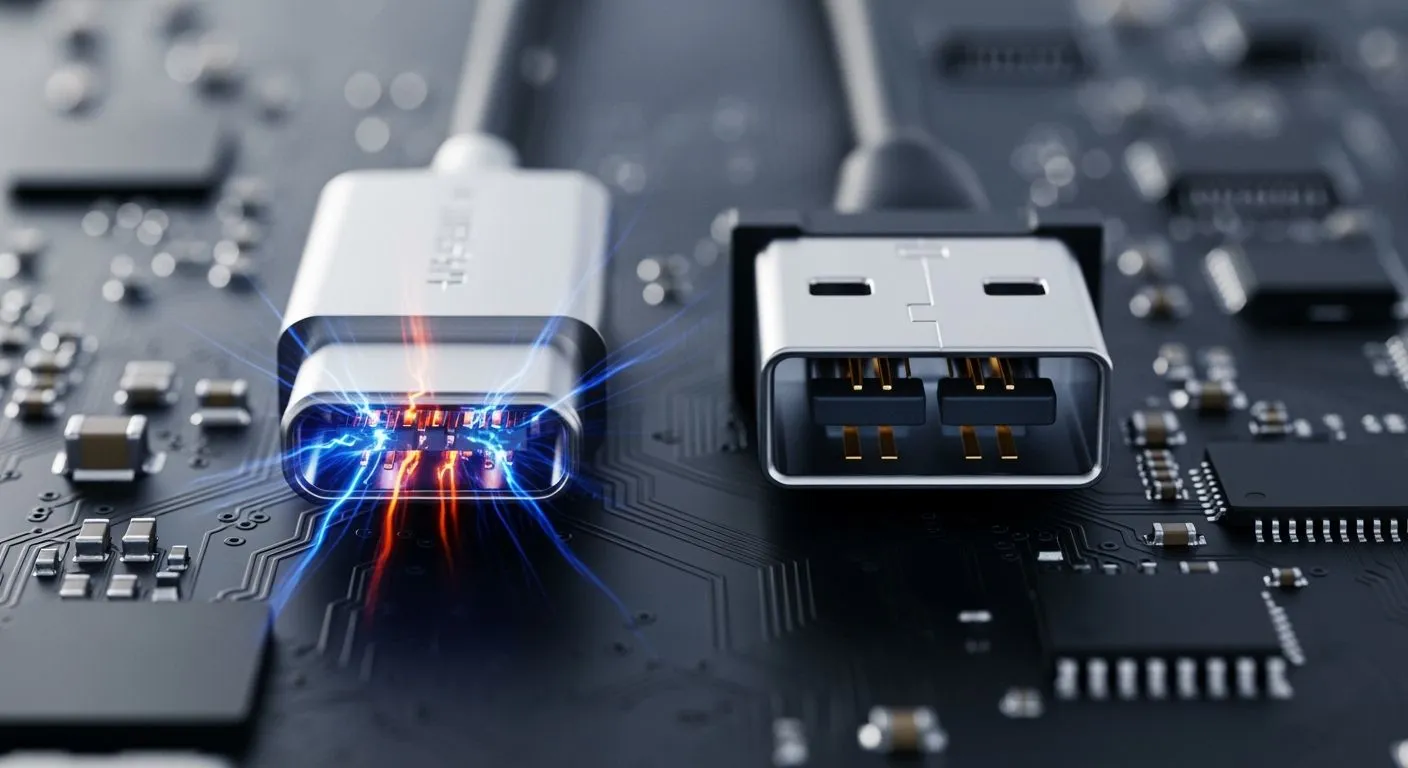
You analyze hardware architecture when evaluating type c vs usb implementations. Legacy universal serial bus protocols define data protocol standards. However, usb c describes a physical 24-pin reversible connector standard. Legacy usb-a ports restrict data transfer speeds across fixed unidirectional pins. The flexible usb-c geometry replaces older usb ports in modern usb c designs. As an authorized HiSilicon-designated solutions partner, Nova Technology Company (HK) Limited develops advanced IC chip-level solutions for modern usb c systems. You can multiplex high-speed data, video signals, and dynamic power delivery up to 240W through one usb c interface. This unified usb-c layout simplifies efficient power transfer in your embedded usb c hardware.
Key Takeaways
- USB-C uses a symmetrical 24-pin connector that allows reversible cable plugging.
- USB-C Power Delivery handles up to 240W of dynamic power through dedicated configuration pins.
- Alternate Mode allows USB-C cables to send high-definition video signals to external monitors.
- Engineers must place separate 5.1kΩ pull-down resistors on CC pins to ensure proper power supply.
- Short differential traces with 90-ohm impedance control protect high-speed data signals from interference.
Type C vs USB Physical Hardware Integration

Modern electronic devices require compact physical design and high-speed standard connectivity. The usb-c connector replaces legacy physical connectors across laptops, smartphones, and embedded system devices. Old usb ports like usb-a, mini-usb, and micro-usb utilize unidirectional pin layouts, but usb c unifies these designs. Modern designs integrate a universal interface standard into a usb c layout to handle high power and rapid data transfer over usb bus lines.
Pinout Evolution: Legacy USB to 24-Pin USB-C
Legacy usb system architectures rely on simple physical layouts. The basic usb 2.0 interface uses a 4-pin layout, while usb 3.0 expands to 9 pins. In contrast, the usb c standard uses a symmetrical 24-pin geometry.
| Pin Group | USB-C (24-pin) Functions & Count | Traditional USB 2.0 (4-pin) Comparison |
|---|---|---|
| Power | VBUS: 4 pins (A4, A9, B4, B9) up to 240W. GND: 4 pins (A1, A12, B1, B12) for return current. | Single VCC and single GND pin, limited to lower current (typically ≤ 500mA). |
| Configuration & Control | CC1 / CC2: 2 pins for orientation and power communication. | N/A. The 4-pin connector has no dedicated control channel. |
| Data (Legacy) | D+ / D-: One differential pair (A6/A7 shorted to B6/B7) for data up to 480 Mbps. | D+ / D-: One differential pair for standard data routing. |
| Data (High-Speed) | TX/RX Pairs: Four shielded differential pairs (TX1±, RX1±, TX2±, RX2±). | N/A. Lacks high-speed data lanes beyond usb 2.0. |
| Sideband | SBU1 / SBU2: 2 auxiliary pins (A8, B8) for alternate mode signals. | N/A. No sideband capabilities. |
This expanded pin grid allows you to run high-speed signals and high power rails through one physical usb c interface. Managing usb c port signals requires precise routing.
The symmetrical architecture of usb c enables reversible plug insertion through a specific detection sequence:
- The symmetrical usb-c pinout provides two Configuration Channel pins, CC1 and CC2.
- Upon plug insertion, only one CC pin makes an electrical connection between the plug and receptacle.
- The source port (DFP) has a pull-up resistor (Rp) connected to 5V on its CC pins.
- The sink device (UFP) has a pull-down resistor (Rd) connected to ground on its CC pins.
- Connected resistors form a voltage divider on the single active CC line.
- Logic circuitry in the source port measures the resulting voltage on this line.
- By detecting which specific CC pin presents this voltage, the source determines physical plug orientation.
PCB Footprint and Surface-Mount Anchoring
When you evaluate mechanical durability in a hardware design, type c vs usb comparisons show significant structural differences. Legacy usb-a receptacles lack standardized durability metrics across manufacturers. Hardware specifications highlight clear mechanical limits when deploying usb c power in standard usb hardware.
| Connector Type | Specified Minimum Insertion Cycles | Source of Specification | Notes |
|---|---|---|---|
| USB-C | 10,000 cycles | USB-IF Type-C Specification R2.3 (section 3.8.1) | Withstands this number of cycles without physical damage. |
| USB-A | Not specified in provided results | No comparable specification data retrieved | No official insertion cycle specification retrieved for usb-a pins. |
Carefully route the dense 24-pin PCB footprint when soldering a usb c connector for a usb c design. Mid-mount and surface-mount receptacle pins require tight manufacturing tolerances to avoid solder bridges. Outer shell tabs anchor directly into ground planes on your board. These through-hole metal posts absorb mechanical stresses when users insert or pull out usb-c cables. This mechanical design protects signal traces, increases durability, and prevents pad lifting when plugging a cable into your legacy usb-a or modern usb c system.
Power Architecture: Legacy USB vs USB C Delivery
Evaluating power architectures reveals major functional distinctions between legacy usb standards and modern usb c power hardware. Legacy configurations rely on fixed voltage rails for power transmission. Modern usb c systems adapt dynamically to changing power requirements in embedded usb c hardware.
Fixed 5V Legacy USB Power Constraints
Legacy architectures supply baseline electrical power using fixed 5V lines. Standard downstream ports provide strictly limited current without specialized communication protocols. System designers used the USB BC 1.2 specification to increase legacy power delivery limits beyond original thresholds.
The USB-IF’s Battery Charging 1.2 specification... requires portable devices to absorb a maximum current of 1500mA (equivalent to three times that of USB 2.0) during charging when connecting to a USB host or a hub.
The table below compares legacy usb port charging behavior across standard downstream ports, charging downstream ports, and dedicated charging ports.
| Port Type | BC1.2 Support | Max Current (at 5V) | USB Data Support | Key Mechanism |
|---|---|---|---|---|
| Legacy SDP | No | 500mA (USB 2.0) | Yes | Standard usb enumeration and configuration required. Unconfigured state allows only 100mA. |
| BC1.2 CDP | Yes | 1.5A (1500mA) | Yes | Employs detection handshake on D+/D- lines. Supplies 1.5A without requiring full usb configuration. |
| BC1.2 DCP | Yes | 1.5A (1500mA) | No | Has fixed resistance bridge between D+ and D- lines. Allows immediate high-current draw. |
These fixed 5V rail limits severely constrain modern usb c hardware. A traditional legacy usb-a port cannot supply sufficient current for demanding laptop or fast-charging applications. You must adopt an advanced usb c port to achieve higher power throughput safely on your compact usb c design.
Dynamic USB-C Power Delivery and CC Logic
The modern usb-c connector replaces rigid legacy power rails with scalable Power Delivery capabilities. Legacy usb-a designs lack dedicated voltage negotiation lines. Modern usb-c cables use specialized Configuration Channel pins (CC1 and CC2) to establish continuous management communication between source and sink controllers on your universal usb c interface.
The table below outlines voltage, current, and maximum wattage limits across evolving standard generations in a direct type c vs usb hardware comparison.
| Specification | Maximum Voltage | Maximum Current | Maximum Power |
|---|---|---|---|
| BC 1.2 (Legacy) | 5 V | 1.5 A | 7.5 W |
| PD 3.0 (Pre-EPR) | 20 V | 5 A | 100 W |
| PD 3.1 with EPR | 48 V | 5 A | 240 W |
The dedicated CC lines manage dynamic power delivery handshakes between connected devices. System hardware executes a structured communication sequence on your integrated usb c circuit during power contract negotiation:
- Initial Capability Assessment: The source device first identifies the capabilities of the connected usb c charging cable.
- Source Capabilities Message: The source transmits a message containing Power Data Objects that detail available voltage and current levels.
- Sink Request: The sink device evaluates available Power Data Objects and transmits a Request Data Object for a specific option.
- Source Decision: The source controller evaluates the request and returns an accept or reject response message.
- Power Adjustment: Upon accepting the request, the source adjusts its internal power rail to output the negotiated voltage and current.
- Confirmation: The source sends a Power Supply Ready message to signal that the sink may safely draw negotiated power.
Robust protection circuits shield sensitive silicon from high-voltage events on shared pins:
- High-voltage protection switches connect in series on CC and SBU lines to isolate circuits when voltages exceed safe operating thresholds.
- Specialized protection ICs achieve rapid 100ns response times with voltage clamps, withstanding surge voltages up to 80V under IEC61000-4-2 ESD standards.
- Initial connection handshakes use a pull-down resistor (Rd) on CC lines to verify device attachment before initiating high-voltage communication.
Implementing these hardware mechanisms ensures safe charging and high-speed data handling in your custom usb c system.
Signal Protocols and USB-C Multi-Function Multiplexing
High-Speed Differential Routing and Reversibility
Reversible plug orientation requires extra signal lines inside the receptacle. You must route duplicate SuperSpeed differential pairs to handle both plug positions. An integrated multiplexer switch selects active differential pairs based on cable orientation. Configuration channel logic detects physical insertion and signals the switch. The multiplexer routes active high-speed lines to your main host controller. Proper routing prevents signal reflection and optimizes data transmission across traces. Modern hardware requires strict layout techniques to achieve maximum data transfer speeds.
| Best Practice Category | Guideline for USB 3.2 Gen 2 (10 Gbps) | Target Rationale |
|---|---|---|
| Impedance Control | Target 90-ohm differential impedance on FR-4. | Prevents signal reflections. |
| Pair Length Matching | Keep mismatch tighter than 0.5mm. | Prevents timing skew. |
| Decoupling | Place 0.1µF and 1µF capacitors near chip pins. | Filters power rail noise. |
Careful trace layout protects signal integrity during high-speed transfer operations. You must keep high-speed differential pairs short and direct on inner PCB layers. Routing traces over a continuous ground plane provides a stable low-impedance return path. These layout rules maintain target data transfer speeds on your custom usb c PCB.
Alternate Modes: Video and PCIe Integration
Alternate Mode allows flexible pin remapping inside physical connector hardware. You can reconfigure high-speed lanes to stream video directly to usb-c monitors. This capability eliminates separate display cables in modern workstations. External usb-c monitors receive high-definition video while sending control signals back to the host. System designers configure lane mapping to maintain fast data transfer speeds for connected equipment. High-end usb-c monitors rely on this flexible architecture for reliable visual output.
- Flexible partitioning supports two 8.1 Gbps video lanes alongside two 10 Gbps lanes for usb data handling.
- Full four-lane allocation drives high-resolution displays, while dedicated pins handle usb 2.0 data transfer.
- Dedicated sideband pins manage auxiliary communication between the host and external usb-c monitors.
The USB4 specification supports PCIe tunneling over physical connector hardware. Encapsulation processing creates an effective throughput of 2.86 GB/s for external eGPU enclosures. Hardware designers connect external graphics cards and high-resolution usb-c monitors through one unified usb c interface. This design accelerates data transfer operations across your board. You can deploy a compact usb c port that delivers high data transfer speeds for desktop peripherals. Designers build a versatile usb c product that maintains peak data transfer speeds under heavy load. Efficient usb c controllers improve bus efficiency for every connected usb c hardware peripheral. Every embedded usb c system benefits from unified high-speed connectivity. You can easily integrate an advanced usb c port into your next usb c project.
Hardware Implementation for USB C Systems
Thermal Management and ESD Protection
High-power charging scenarios demand careful thermal management across your usb c hardware. Selecting thin 32 AWG cable conductors causes unsafe temperature rise above 65°C within 90s under 3A loads. You must place thermal sensors near the integrated usb c connector. Real-time sensors trigger dynamic power throttling logic to protect connected devices. You can also deploy thermal vias on your board to dissipate heat efficiently. Nova Technology Company (HK) Limited provides advanced IC chip-level solutions as an authorized HiSilicon-designated solutions partner. Their embedded semiconductor designs help engineers maintain optimal thermal margins during high-current system operation.
Electrostatic discharge damages sensitive usb chips during daily operation. You should place transient voltage suppression diodes extremely close to the physical usb-c port. Dedicated protection ICs follow the IEC 61000-4-2 standard to stop high-voltage spikes. High-speed data lines require low-capacitance diodes like the Semtech RClamp3371ZC. This diode offers 0.25pF maximum capacitance with ±17kV air discharge protection. Maintaining low capacitance prevents signal degradation during high-speed data handling.
Legacy USB Backwards Compatibility Circuits
You can easily connect legacy usb-a peripherals to modern hardware interfaces. Simplifying pin selection helps you integrate usb-c technology into space-constrained usb c designs. You can ignore high-speed lanes and connect only VBUS, GND, D+, D-, and CC lines. However, incorrect CC termination creates major power delivery failures. Connecting both CC lines together breaks host detection completely. You must place a separate 5.1kΩ pull-down resistor on each CC pin. This proper termination allows a standard legacy host to supply power safely across the usb c layout.
Inrush currents on VBUS lines can trigger host power protection circuits. You should install a dedicated power distribution switch to limit current slew rates below 150mA/μs. Compact IoT designs must also comply with low-power suspend standard requirements. Unused bus lines must draw 2.5mA or less after 7ms of inactivity. You can use specialized usb control chips to handle suspend logic automatically. Simple usb-a legacy adapters adapt these signals seamlessly. Correct trace routing ensures reliable usb performance across every legacy usb design. You can optimize your usb c board footprint by maintaining strict layout practices for each usb module. Deploying a robust usb c module ensures complete backward compatibility for every legacy usb standard.
Transitioning your hardware designs from legacy usb ports to a usb-c connector requires careful planning. Evaluating type c vs usb specifications reveals major board updates. You must place separate 5.1kΩ pull-down resistors on CC pins. Proper termination prevents logic errors across your usb system. Routing high-speed usb data lines demands precise 90-ohm differential impedance control. You must also place protection diodes near the usb c connector.
Mastering integrated usb c layout unlocks outstanding performance. A single usb c port handles rapid data transmission alongside dynamic power delivery. You can construct compact electronics using a versatile usb c module. Every modern usb c board benefits from unified usb capabilities.
FAQ
What is the main structural difference in legacy usb and modern usb c hardware?
When you evaluate type c vs usb designs, physical symmetry stands out. A modern usb c port uses a reversible layout. Legacy usb-a ports use fixed unidirectional pins, limiting overall data transfer speeds. Connecting external usb-c monitors requires an integrated usb c connector for high-speed routing.
Why do external usb-c monitors require specialized video routing?
External usb-c monitors use Alternate Mode to rebind high-speed lanes. Modern usb c systems stream high-resolution video while maintaining high data transfer speeds across active lanes. A single usb c cable connects workstations directly to usb-c monitors without extra usb display adapters.
How does dynamic charging operate across modern usb c systems?
Legacy usb ports rely on fixed 5V lines for basic charging. In contrast, modern usb c hardware uses Configuration Channel pins to negotiate fast charging profiles. Connected devices draw power safely while transmitting high data transfer speeds to powered usb-c monitors over a standard cable.
Why do data transfer speeds increase on a usb c interface?
Multiple high-speed differential pairs increase bandwidth. Modern usb c designs achieve fast data transfer speeds for your hardware. Connected usb-c monitors rely on high data transfer speeds to handle video communication, while a high-speed usb hub manages basic data transfer operations.