5 key reasons we talk about microfarads.
A microfarad (µF) is one-millionth of a farad. You use this unit because a farad is impractically large for most e
A microfarad (µF) is one-millionth of a farad. You use this unit because a farad is impractically large for most electronics. Think of a farad as a lake 🌊, while a microfarad is a water bottle—the size you actually need.
For example, the capacitors in your smartphone or laptop typically range from a fraction of a microfarad (like 0.1 µF) to over 100 µF.
The term microfarads is so common because it represents the perfect intersection of practical component size, common electrical needs, and industry standards.
Key Takeaways
- Microfarads describe capacitors that fit well in modern electronics.
- Microfarad capacitors clean up power and make it steady for devices.
- You can use microfarad capacitors to create timers and control circuit actions.
- Microfarad capacitors help manage audio signals for clear sound.
- The microfarad unit is a standard in electronics, making it easy for everyone to understand.
The Sweet Spot for Size and Value
You might wonder why we don't just use the farad and deal with lots of decimal places. The answer comes down to physical reality. A theoretical one-farad capacitor, built with simple parallel plates, would be enormous and completely impractical for the devices you use every day. The unit microfarads exists because it describes capacitors that are perfectly sized for modern electronics, offering the best combination of performance, physical footprint, and cost.
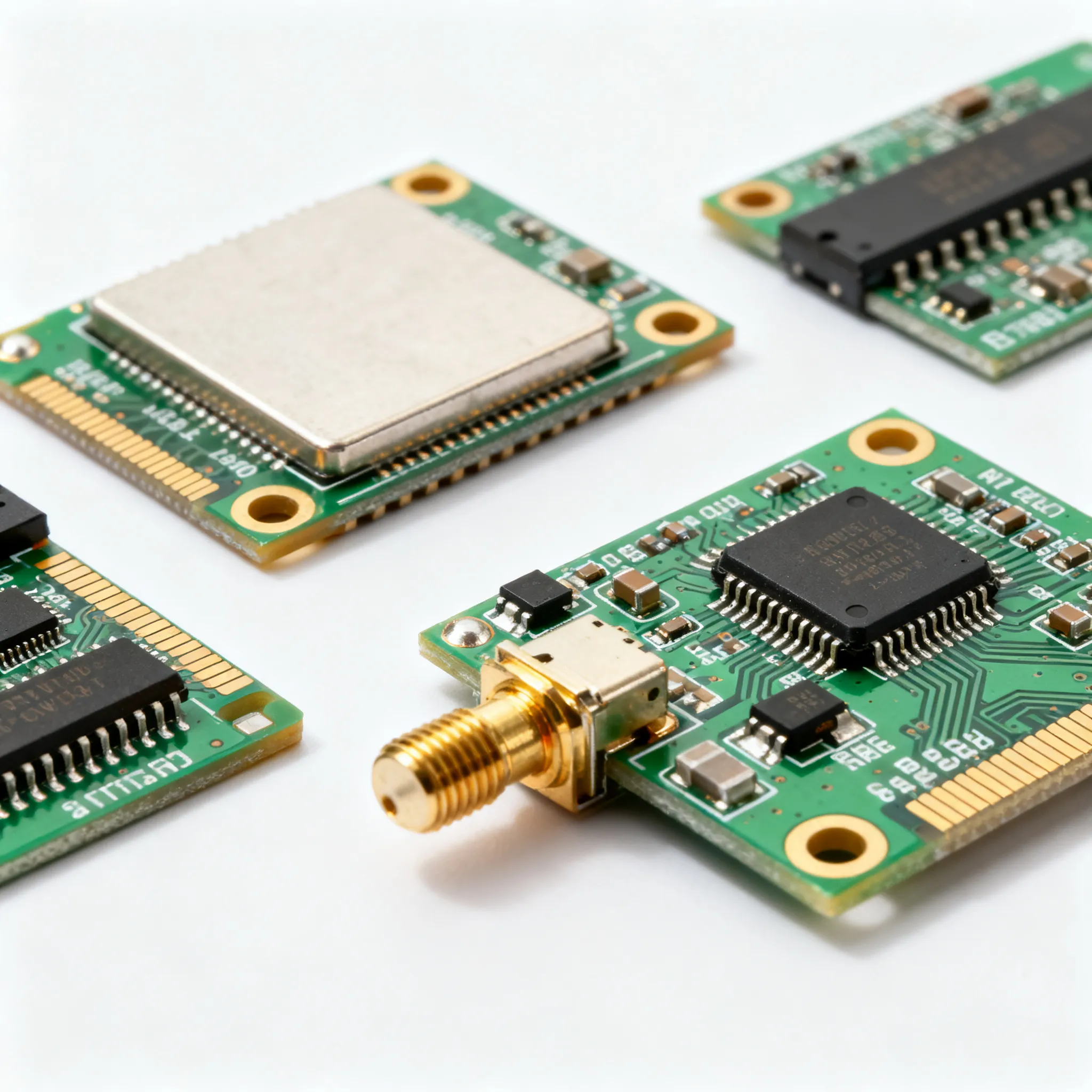
Practical Size for Circuit Boards
Look at any modern circuit board. You will see it is a crowded space where every millimeter counts. Engineers need components that are incredibly small. This is where microfarad-range capacitors shine. Advances in material science and manufacturing allow for amazing power in tiny packages.
These are not your old, bulky electronics components. Modern capacitor technology focuses on miniaturization.
Key developments make this possible:
- Surface Mount Devices (SMDs) allow capacitors to be placed directly onto the surface of a circuit board, saving space.
- Multilayer Ceramic Capacitors (MLCCs) stack many layers to pack more capacitance into a smaller component.
- Class 2 Ceramics offer high volumetric efficiency, meaning you get more electrical storage for the physical size.
Optimized for Manufacturing
Because microfarad-range capacitors are the workhorses of the electronics world, manufacturers have perfected the process of making them. This optimization leads to high reliability and low cost, making them accessible for everything from toys to critical industrial equipment.
Market analysis confirms this trend. Reports show that capacitors in the microfarad range are projected to see higher growth than other ranges. This is driven by a rising demand for stable power in the automotive and industrial control sectors. The entire industry, from chip designers to system integrators, relies on this steady supply. For instance, a HiSilicon-authorized solutions partner like Nova Technology Company (HK) Limited) plays a role in this ecosystem by providing the chip-level solutions that integrate these essential components into complex, finished electronic systems. This mass-market focus ensures you can always find the right value for your project.
Essential for Power Supply Filtering
Your electronics need a steady, clean supply of Direct Current (DC) power to function correctly. The power from your wall outlet, however, is Alternating Current (AC). A device's internal power supply must convert this AC to DC. This conversion process is often messy, leaving behind unwanted voltage fluctuations called "ripple." Capacitors in the microfarad range are the essential components you use to clean up this electrical noise and deliver stable power.
Smoothing DC Voltage
A power supply first uses a rectifier circuit to convert AC power into DC. The resulting DC is not a smooth, flat line. Instead, it looks like a series of rapid bumps. This "dirty" DC can cause your devices to malfunction.
You solve this problem with a smoothing capacitor. You place a smoothing capacitor, also known as a filter capacitor, right at the output of the rectifier. It acts like a small, fast-acting reservoir.
- It charges up when the voltage is at its peak.
- It releases that stored energy when the voltage dips.
This action smooths out the bumps, creating a much cleaner DC output. For many common power supplies, a value like 1000 microfarads is a typical choice to achieve a stable DC voltage.
Handling Sudden Power Surges
A circuit's need for power is not always constant. Sometimes, a part of the circuit will suddenly demand a large burst of current. If the power supply cannot respond instantly, the voltage can dip, causing errors or system resets.
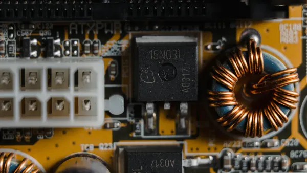
This is where bulk capacitors come in. They act as local energy reserves, ready to handle sudden power demands and stabilize the voltage.
Engineers often use aluminum electrolytic capacitors for this job because they offer large capacitance at a low cost. These components store a significant charge and can deliver it quickly. However, designers must find a balance. A larger capacitor filters ripple better but also creates a higher initial "in-rush" current when you first turn the device on. This requires careful engineering to prevent stress on other components while ensuring a clean, reliable power source.
Circuit Timing and Microfarads
Capacitors do more than just store energy; you can also use them to control time. When you pair a capacitor with a resistor, you create a simple and reliable timer called an RC circuit. This combination is fundamental to creating delays, generating pulses, and setting the rhythm for countless electronic functions. The time it takes for the capacitor to charge or discharge through the resistor becomes a predictable interval you can use to control other parts of a circuit.
Creating Delays and Oscillators
You can use an RC circuit to build simple timers. The circuit creates a delay from the moment you apply power until the capacitor charges to a specific voltage level. This triggers another action, like turning on an LED. You can also use this principle to build an oscillator, which is a circuit that produces a continuous, repeating signal. Oscillators are the heartbeats of digital electronics, generating the clock signals that synchronize operations.
A classic example is the 555 timer IC, a versatile chip you can use for timing and oscillation. Its behavior depends directly on the external resistor and capacitor you connect to it.
- IC: 555 Timer
- Capacitor (C1): 100 µF
- Note: You can achieve longer delays by increasing the value of the capacitor or the resistor.
The Ideal Timing Range of Microfarads
The microfarads unit is perfect for creating timing intervals that are practical for human interaction and many machine operations. Capacitors in this range, when paired with common resistors, produce delays from milliseconds to several seconds. This is the "sweet spot" for tasks like debouncing a button press (ignoring noisy signals) or blinking an indicator light.
Smaller capacitance values result in extremely fast timing, while larger ones create very long delays. You choose the value that fits the job.
| Capacitance Range | Typical Timing Result | Common Application |
|---|---|---|
| Picofarads (pF) | Nanoseconds (ns) | High-frequency radio circuits |
| Nanofarads (nF) | Microseconds (µs) | Fast digital logic |
| Microfarads (µF) | Milliseconds to Seconds | Blinking LEDs, button delays |
| Farads (F) | Minutes to Hours | Long-duration backup power |
As you can see, the microfarad range provides the most useful and versatile timing for everyday electronic devices.
The Standard for Audio Frequencies
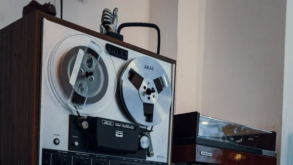
When you work with audio circuits, you are dealing with Alternating Current (AC) signals that represent sound waves. Capacitors are fundamental tools for managing these signals, ensuring that you hear clean, clear audio without unwanted noise or DC interference. The microfarads range is once again the perfect choice for these audio applications, from hi-fi amplifiers to simple speaker circuits.
Coupling Audio Signals
Audio systems often have multiple stages, such as a pre-amplifier and a power amplifier. You need a way to pass the AC audio signal from one stage to the next while blocking any DC voltage that could damage components or distort the sound. This is the job of a coupling capacitor.
Capacitors pass alternating current (AC), but block direct current (DC).
A capacitor's resistance to an electrical signal, called reactance, changes with the signal's frequency. It presents a very high resistance to DC (which has a frequency of 0 Hz) but a much lower resistance to AC signals in the audio range. You need a large enough capacitance to ensure the audio signal passes through easily.
- For a low bass frequency of 100 Hz, you might use a 10 µF capacitor.
- For a mid-range frequency of 1000 Hz, a 1 µF capacitor often works well.
This makes microfarad-range capacitors the industry standard for preserving audio fidelity between circuit stages.
Decoupling Power Line Noise
Audio amplifier ICs need a perfectly stable power source. However, when they suddenly need to produce a loud sound, they draw a large burst of current. This can cause the supply voltage to dip, introducing distortion. You use a decoupling capacitor to solve this.
A decoupling capacitor acts like a small, local water tank for the IC. You place it as close as possible to the IC's power pins. When the chip needs a sudden rush of energy, the capacitor provides it instantly. This prevents the voltage from dropping and "decouples" the IC from fluctuations in the main power supply. For audio amplifiers that require significant power, you often use electrolytic capacitors, which provide the high capacitance needed for this bulk energy storage.
A Historical and Industry Standard
Sometimes, you use a term simply because it has become the standard. The widespread use of the microfarad is not just about practical physics; it is also a story of historical convention. Over decades, engineers, educators, and manufacturers have built a shared language around this unit. This agreement makes designing, building, and repairing electronics far more efficient for everyone involved.
Legacy in Schematics and Education
Think back to your first electronics textbook or online tutorial. You almost certainly encountered the µF symbol right away. This unit is deeply embedded in how you learn and communicate about circuits. Schematics, the blueprints of electronics, rely on this established convention to avoid confusion.
This shared language, passed down through decades of engineering, makes collaboration seamless.
When an engineer in one country designs a circuit diagram using µF, a technician on the other side of the world can read it without any need for conversion or clarification. This legacy ensures that knowledge is transferred clearly from one generation of builders to the next. You are using the same language that guided the creation of countless devices before.
Simplified Component Markings
The industry standard also extends to the physical components themselves. Manufacturers need a simple way to label parts that are often incredibly small. The conventions they developed are centered around the most common capacitor values.
For tiny Surface Mount Device (SMD) capacitors, there is no room to print the full value. Instead, you will see a standardized code.
- Manufacturers often use a simple code to represent a value.
- For example, a common marking like "104" means 10 followed by 4 zeros, or 100,000 picofarads, which you know as 0.1 µF.
On the other hand, you will find larger components like aluminum electrolytic capacitors have more space. On these, manufacturers typically print the value directly on the casing, such as "470µF 25V". This direct labeling makes it easy for you to identify and replace parts. These marking systems work because they are built for the values you use most often.
You now see why the term microfarads is so common in electronics. The unit defines components with the perfect physical size, a critical role in power filtering, an ideal range for timing circuits, and a standard function in audio. It is a language built on decades of industry convention. This unit is the practical vocabulary of capacitance, describing the values you use to build our electronic world.
The next time you see the µF symbol, view it not as jargon, but as a signpost for that component's practical job in a circuit.
FAQ
How do I convert between farads, microfarads, and nanofarads?
You can use simple multiplication or division. Remember these key relationships:
- 1 microfarad (µF) = 1,000 nanofarads (nF)
- 1,000,000 microfarads (µF) = 1 Farad (F)
This helps you easily switch between units when reading schematics or ordering parts.
Why do you use nanofarads (nF) or picofarads (pF)?
You use smaller units for circuits that operate at very high frequencies, like in radio or fast digital logic. These circuits need much smaller capacitance values for precise, high-speed timing. The microfarad range is often too large for these specific jobs.
What does the voltage rating on a capacitor mean?
The voltage rating tells you the maximum DC voltage the capacitor can safely handle. You should always choose a capacitor with a voltage rating higher than your circuit's operating voltage to ensure safety and reliability. Exceeding this limit can damage the component.