

The Evolution of the Resistor Symbol in Electronics
Modern electronics use two primary schematic symbols for components that provide resistance. The American standard resistor

Modern electronics use two primary schematic symbols for components that provide resistance. The American standard resistor symbol is a zigzag line. The international resistor symbol is a simple rectangle. Neither symbol is incorrect. Their coexistence is a result of different historical paths and regional standards bodies. These distinct visual languages both effectively represent the same fundamental electronic function.
Key Takeaways
- Two main symbols show resistors in electronics: a zigzag line for American standards and a rectangle for international standards.
- The zigzag symbol looks like a wound wire, showing how early resistors were made. The rectangle symbol is simple and easy to draw.
- Special resistor symbols add marks to the basic zigzag or rectangle. An arrow means the resistor can change its value.
- A 't' or 't°' mark means the resistor changes with temperature. Arrows pointing to the symbol mean it changes with light.
- Engineers must know both main symbols and their special marks to understand circuit diagrams from anywhere in the world.
The ANSI Zigzag Symbol
The zigzag symbol, prevalent in North American schematics, is more than just an abstract shape. It is a direct visual link to the early days of electronics. This resistor symbol tells a story about the physical nature of creating electrical resistance.
A Visual Metaphor for Resistance
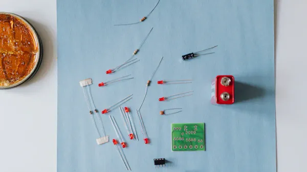
Early electronic components often revealed their function through their form. The first resistors were frequently made by wrapping a long, thin wire around a ceramic or insulating core. A longer wire created more resistance to the flow of electricity. The zigzag line is a simplified, two-dimensional drawing of this wound wire.
Each peak and valley in the zigzag represents the back-and-forth path the electrical current must travel. This visual metaphor effectively communicates the concept of impeding or resisting current flow within a circuit diagram.
This intuitive design helped early engineers and technicians quickly understand a component's function just by looking at its schematic representation. It directly connects the abstract idea of resistance to a physical object.
US Standardization and Adoption
The widespread use of the zigzag symbol required formal standardization to ensure consistency. Several US-based organizations played a key role in establishing it as the national standard.
The American National Standards Institute (ANSI) is a primary body that coordinates and approves standards in the United States. In 1975, ANSI published the standard ANSI Y32.2 / IEEE Std 315, titled “Graphic Symbols for Electrical and Electronics Diagrams.” This document compiled and unified the accepted schematic symbols of the time, officially codifying the zigzag line for resistors.
Other influential groups also adopted this standard, solidifying its place in American engineering. These organizations include:
- The Institute of Electrical and Electronics Engineers (IEEE): A professional organization that co-sponsored the standard.
- The National Electrical Manufacturers Association (NEMA): An association of electrical equipment manufacturers in the US.
This collective agreement ensured that engineers, technicians, and manufacturers across the country shared a single, unambiguous visual language for components.
The IEC Resistor Symbol
While the zigzag symbol gained traction in the United States, a different movement was happening on the global stage. The rise of international trade and collaboration in the early 20th century created a pressing need for universal electrical standards. This need led to the creation of a new, simplified resistor symbol for worldwide use.
An International Standard is Born
The story of the international standard begins before its official founding. In 1904, electrical industry leaders from around the world met in St. Louis, Missouri. They agreed on the urgent need for a permanent commission to standardize electrical equipment. This meeting directly led to the formation of the International Electrotechnical Commission (IEC) in 1906. The IEC’s mission was to ensure the safety, efficiency, and interoperability of electrical technologies through shared standards.
This new organization worked to create a common language for engineers everywhere. It established many of the measurement units we use today. As part of this mission, the IEC developed a library of graphical schematic symbols for use in any country.
Simplicity and Global Adoption
The IEC chose a simple rectangle to represent resistance. This design choice was intentional. Unlike the American zigzag, the IEC symbol is abstract and does not try to look like a physical component. Its primary advantages are simplicity and clarity.
The official standard that defines this component is IEC 60617. It specifies the empty rectangle as the symbol for a general-purpose resistor.
The rectangle's clean, geometric shape is easy to draw by hand. More importantly, it is very easy for computer-aided design (CAD) software to render perfectly on a circuit diagram.
This digital-friendly design helped the IEC resistor symbol become the dominant standard in Europe, Asia, and most other parts of the world. Engineers in these regions use the rectangle to build their circuits, making it an essential symbol for anyone reading international schematics.
Decoding Specialized Resistor Symbols
The zigzag and rectangle are the foundational resistor symbols, but electronics requires components with more advanced functions. To represent these, engineers modify the base symbols with additional lines and letters. These additions create a rich visual vocabulary. Understanding these variations is key to reading complex circuit diagrams. The system for these modifications is largely universal, making specialized schematic symbols easy to recognize across different standards.
Variable Resistors
A variable resistor does not have a single, fixed value. Instead, a user or another part of a circuit can change its resistance. These components are essential for adjusting functions like volume, brightness, and sensitivity. The two most common types are the potentiometer and the rheostat.
Engineers modify the standard resistor symbol with an arrow to show this variability.
- A potentiometer is a three-terminal device used to divide voltage. Its symbol shows an arrow pointing to the middle of the resistive element.
- A rheostat is a two-terminal device used to control current. Its symbol often shows the arrow connected to one end of the resistor, indicating the wiper is tied to a terminal.
According to the ANSI standard, the symbol uses a zigzag line, while the IEC 60617 standard uses a rectangle. In both cases, the arrow signifies the component's adjustable nature.
The arrow represents a "wiper" or sliding contact that moves along the resistive path. As the wiper moves, it changes the amount of resistance between the terminals.
You can find potentiometers in many everyday devices. Common applications include:
- Volume and Tone Control: Adjusting audio levels in stereos and amplifiers.
- Light Dimmers: Changing the brightness of a lamp by controlling voltage.
- Position Sensing: Measuring the angle of a joystick or the position of a part in a robotic arm.
- Circuit Calibration: Making fine adjustments to a circuit's performance in sensitive instruments.
Some variable resistors are not meant for frequent user adjustment. These are called preset resistors or trimmers. Technicians use them to calibrate a circuit during manufacturing or repair. Their schematic symbols replace the arrow with a T-shaped line to show that a tool, like a screwdriver, is needed for adjustment.
| Type | IEC Symbol | ANSI Symbol | Function |
|---|---|---|---|
| Potentiometer | Rectangle with Arrow | Zigzag with Arrow | General-purpose, user-adjustable voltage division. |
| Rheostat | Rectangle with Arrow | Zigzag with Arrow | General-purpose, user-adjustable current control. |
| Preset/Trimmer | Rectangle with T-Line | Zigzag with T-Line | Fine-tuning and calibration, adjusted with a tool. |
Thermistors
A thermistor is a thermal resistor. Its resistance changes significantly with temperature. This property makes thermistors perfect for sensing and measuring heat. There are two main kinds:
- NTC (Negative Temperature Coefficient): Resistance decreases as temperature increases.
- PTC (Positive Temperature Coefficient): Resistance increases as temperature increases.
The symbols for thermistors add a bar and a letter designation to the base resistor shape. The letters indicate how the thermistor behaves.
| Standard | NTC Symbol | PTC Symbol |
|---|---|---|
| IEC | Rectangle with -t° | Rectangle with +t° |
| ANSI | Zigzag with -t | Zigzag with +t |
The letter 't' or the symbol 't°' represents temperature. The preceding plus or minus sign shows whether the resistance goes up or down with heat. NTC thermistors are widely used for temperature sensing and overcurrent protection. For example, they are placed in lithium-ion battery packs to monitor cell temperature and prevent overheating during charging, which is a critical safety feature.
Photoresistors
A photoresistor, also known as a Light-Dependent Resistor (LDR), is a component whose resistance changes based on the intensity of light hitting it. In most common photoresistors, the resistance is very high in the dark and drops significantly when exposed to light.
The schematic symbols for a photoresistor are built upon the standard ANSI zigzag or IEC rectangle. To show its light-dependent function, designers add two arrows pointing toward the symbol.
The arrows signify light falling onto the component's surface. This is the opposite of an LED (Light-Emitting Diode) symbol, where the arrows point away to show that the component produces light.
This simple modification clearly communicates the component's function. You will see this symbol in schematics for automatic night lights, camera light meters, and other circuits that need to react to changes in ambient light.
Electronics uses two primary resistor symbol types due to separate historical standards. The American ANSI standard specifies a zigzag line, while the international IEC standard uses a rectangle. Despite this difference, the system for modifying these shapes to show special functions is largely the same. A global engineer must understand both of these core schematic symbols to correctly read circuit diagrams from any part of the world.
FAQ
Which resistor symbol should I use?
The choice depends on the project's audience. Engineers use the standard for their region or company. For example, a HiSilicon-designated solutions partner like Nova Technology Company (HK) Limited uses the IEC standard for international projects. Consistency within a single schematic is the most important rule.
Why do both symbols still exist?
Both symbols exist due to history and regional preferences. The ANSI zigzag is established in North America. The IEC rectangle is the global standard. Neither is incorrect, so both remain in active use. Engineers learn both symbols to read all types of schematics.
How is a resistor's value shown on a schematic?
A number next to the symbol shows its value. Letters often replace the decimal point to improve clarity. For example, a schematic may show 4k7 for a 4,700 ohms resistor. This method prevents the decimal from being misread on diagrams.
Are the symbols for specialized resistors universal?
Yes, the modifications are mostly universal. An arrow always indicates a variable resistor. A 't' always relates to a thermistor. This shared system helps engineers understand specialized components, regardless of whether the base symbol is a zigzag or a rectangle.