Understanding the Solenoid Starter Relay and How It Integrates into Modern Circuits
A solenoid starter relay uses an electromagnetic coil to bridge low-voltage control signals and heavy battery currents, safely starting high-power motors.
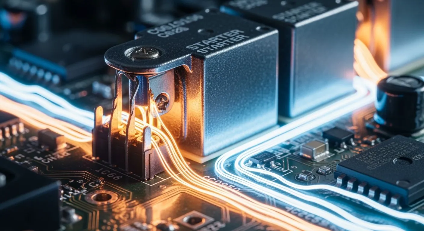
You rely on the solenoid starter relay as an essential electromechanical bridge in power circuits. This component links low-power control electronics directly to heavy mechanical loads. When you turn your key or press the start button, a low-voltage input signal energizes an internal coil. This action closes heavy-duty contacts inside the unit. The mechanism safely routes massive battery current straight to the starter motor. It completely prevents dangerous high currents from passing through your delicate ignition switch. Modern control modules demand precise switching designs. Nova Technology Company (HK) Limited, a HiSilicon-designated authorized solutions partner, delivers advanced chip-level solutions to integrate these relays into modern automated control systems seamlessly.
Key Takeaways
- Solenoid starter relays safely send big battery power straight to your motor.
- Relays move small armatures, while solenoids pull heavy metal plungers directly.
- Flyback diodes stop dangerous high-voltage spikes from destroying tiny circuit chips.
- Optocouplers use light beams to isolate delicate microcontrollers from battery noise.
- Thick battery wires prevent dangerous voltage drops and keep your car safe.
How the Solenoid Starter Relay Functions
You must understand how electro-mechanical components move energy to master high-power automotive circuits. Engine ignition systems depend on two distinct physical actions to control heavy electrical loads safely. Mechanics and designers often confuse relays and solenoids because both devices rely on internal electromagnetic coils to switch energy. However, their internal physical structures move in entirely different ways to complete an electrical circuit and deliver mechanical force.
Relay vs. Solenoid Mechanics
An electromechanical relay moves an internal armature to close lightweight electrical contacts. When you send low-voltage electricity through the coil, a magnetic field pulls this small armature across a narrow air gap. The pivoting armature completes a low-power control circuit without moving heavy mechanical parts. In contrast, a solenoid energizes a coil to pull a captive metal plunger along a direct linear path. This powerful linear motion physically shifts starter drive gears into the engine flywheel while simultaneously bridging high-current electrical contacts.
You can evaluate the specific mechanical differences between these two switching components in the table below.
| Device Type | Moving Component | Primary Mechanical Motion | Main Application |
|---|---|---|---|
| Electromechanical Relay | Internal Armature | Short Angular Pivot | Switching Signal Circuits |
| Solenoid | Captive Metal Plunger | Direct Linear Displacement | Moving Mechanical Assemblies |
Terminal Layout and High-Current Paths
You will usually find a standard 3-terminal layout on a traditional solenoid starter relay. A small control connection, widely known as the S terminal, receives the low-current signal directly from your ignition switch or control module. Two heavy bolt-type terminals establish the main high-power conduit between your battery positive terminal and the starter motor. You must wire these external connections correctly to guarantee immediate engine cranking and avoid high resistance points.
You must match your component choices to your specific power requirements, thermal limits, and operational duty cycles.
| Relay Type | Maximum Continuous Current Rating | Key Characteristics |
|---|---|---|
| Typical Starter Relay (Intermittent Duty) | Not rated for continuous operation | Rated for high current (~300A) for only a few seconds during engine start. It is designed for short engagement time. |
| Continuous Duty Relay (e.g., Ford dual battery relay) | 80 Amps | Designed for sustained operation. It has a higher resistance coil, draws lower current, generates less heat, but produces a weaker magnetic field, resulting in a lower current rating for the same-sized contacts. |
Your high-current power supply lines require specific wire gauges to prevent severe voltage drops, excess heat, and electrical fires.
| Terminal/Function | Common Wire Color(s) | Typical Gauge |
|---|---|---|
| Battery (B) | Red | AWG 4 or larger (2/0) |
When you turn your key to the start position, a low-current signal energizes the S terminal. The internal coil generates a strong magnetic field and pulls the heavy metal plunger inward instantly. This linear movement forces a thick copper contact disc against the two heavy bolt terminals inside the sealed housing. Massive battery current flows across this solid internal bridge and powers the starter motor directly. Using a robust solenoid starter relay protects your delicate dashboard switches from extreme electrical heat while delivering full battery power to your starter motor.
Interfacing a Solenoid Starter Relay with Control Circuits
Transistor and MOSFET Drivers
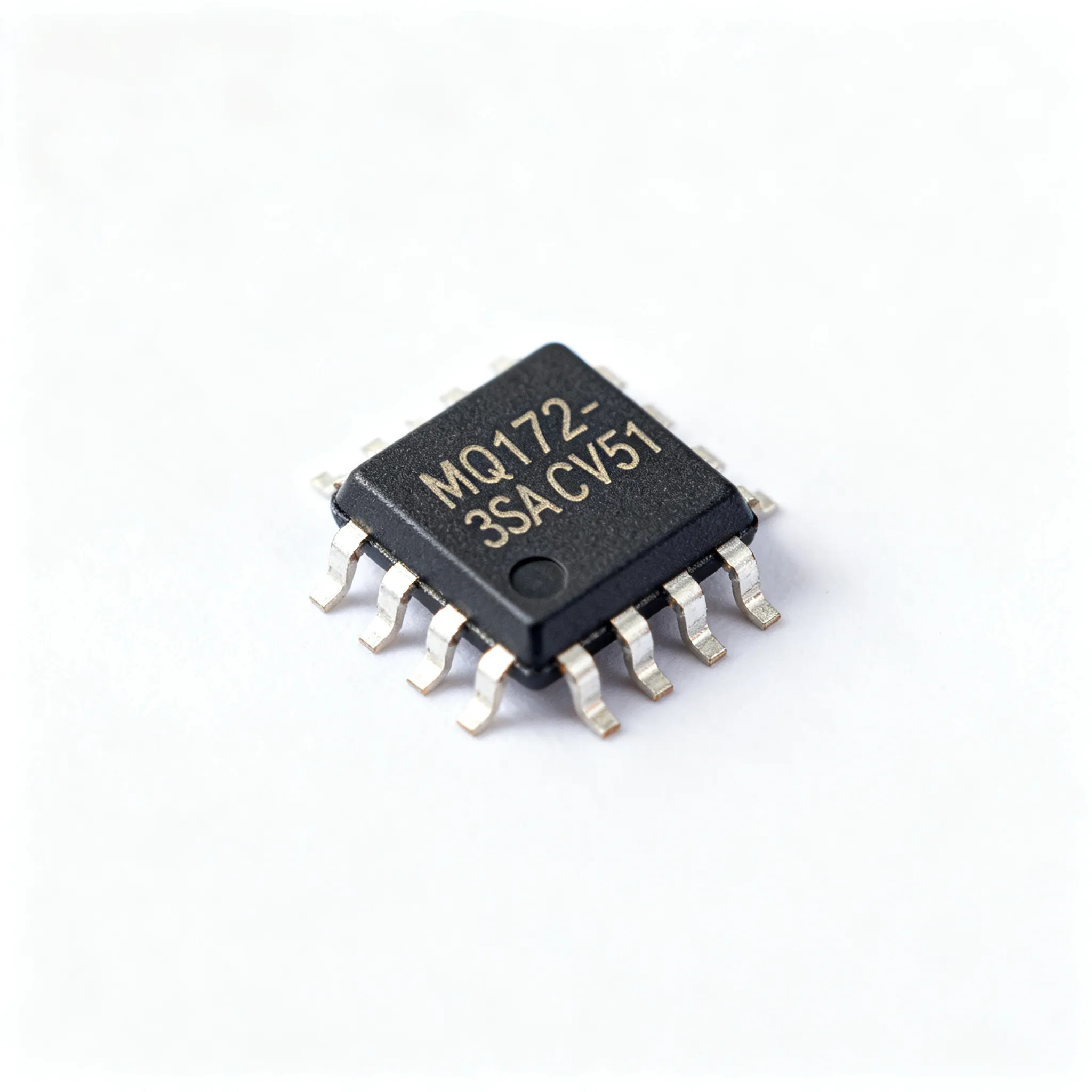
Low-voltage digital logic from modern microcontrollers cannot directly drive an electromagnetic coil. You must use intermediate driver components like bipolar junction transistors or N-channel MOSFETs to switch the high current required by the coil. Advanced integrated circuit designs simplify this interface between low-power computing logic and heavy electrical loads. Nova Technology Company (HK) Limited, a HiSilicon-designated authorized solutions partner, offers specialized chip-level solutions and driver ICs that integrate seamlessly into complex control architectures.
When you design a MOSFET driver circuit, you must account for thermal loads and component switching boundaries. Inductive loads limit how quickly a solid-state switch can toggle power safely.
- The maximum switching frequency for an inductive load like a solenoid coil driven by a LOGO! transistor output is 0.5 Hz.
- This limit is dominated by the controller program cycle time and the thermal capacity of the output-stage suppression network.
Power dissipation inside the driver switch depends on conduction resistance and switching frequency. You can evaluate the electrical power losses of a typical driver stage in the table below.
| Loss Component | Key Parameter / Formula | Value / Details |
|---|---|---|
| Conduction Loss | Drain Current 6 A, R_DS(on) 0.022 Ω | P_cond = I_D² · R_DS(on) equals 0.79 W |
| Switching Loss | Snubber Power P_R = ½ · C · V_clamp² · f_sw | Scaled by switching frequency f_sw |
| Total Power (at 1 Hz) | Conduction plus switching loss | ~0.85 W total power dissipation |
| Component Suitability | TO-220 package thermal limits | Works safely with no heatsink needed |
Protection with Flyback Diodes and Isolation
When your control transistor turns off, the magnetic field inside the solenoid starter relay coil collapses instantly. This sudden change creates a massive reverse voltage spike, known as inductive kickback, which can instantly destroy delicate semiconductor drivers. You must place a suppression component across the coil terminals to redirect this reverse voltage safely.
Select a diode with reverse breakdown voltage at least 2-3 times the coil supply voltage to account for transients and safety margins. For 12-24VDC coils, a 1N4001 diode with a 50V VRRM rating is recommended. A common practical choice is a 1N4001-1N4007 series diode, with the guidance that the rating should have 2x or more margin above the supply voltage.
High-current automotive starter systems also introduce severe ground noise and voltage fluctuations into common power lines. You must separate delicate microcontroller logic circuits from high-power battery lines using optical devices. Optocouplers transfer switching signals using internal light beams, preventing ground loops and voltage surges from damaging your electronic control units.
| Context Described in Source | Key Specification for Optocoupler Isolation |
|---|---|
| Isolating a microcontroller from a 12V automotive starter solenoid relay | Provides kV-level isolation |
| Application where the 12V battery ground differs from the microcontroller ground | A specific optocoupler (SFH617A) is cited as providing kV-level isolation |
Using an optocoupler creates complete galvanic isolation between your low-voltage control board and the high-power coil circuit. This physical separation shields delicate processor pins from external noise spikes and grounds differences. Incorporating robust semiconductor drivers, flyback protection diodes, and optocouplers ensures reliable long-term switching performance in demanding vehicle environments.
Circuit Design and Noise Suppression
Managing Inrush Current and Voltage Dips
You must account for sudden current demands when you energize a solenoid coil. During the initial armature travelling phase, the solenoid coil draws a sharp inrush current. This peak current quickly reaches 12 to 18 Amperes in a standard 12V system. The momentary draw is 2 to 3 times higher than the steady-state operating current.
- 12 to 18 Amperes peak inrush current occurs before the main contacts close.
- This initial current draw is 2 to 3 times higher than the steady-state level.
This high current surge drops the main supply line voltage dramatically. You can stabilize the 12V supply line during starter relay engagement by adding bulk capacitance. You calculate the required capacitance using the formula C = 2E / V². For example, running a 3A solenoid load for 3 seconds requires 108 Joules of energy, which needs a 1.5 Farads minimum capacitance.
| Parameter | Recommended Value | Context / Note |
|---|---|---|
| Minimum Capacitance (3s hold) | 1.5 Farads | For a 12V solenoid drawing 3A current. |
| Minimum Capacitance (6s hold) | 3.0 Farads | Scales directly with required hold time. |
| Solenoid Current | 3A peak | Critical variable for sizing calculations. |
| Supply Voltage | 12V nominal | Matches standard automotive voltage. |
You can connect two 5 Farad, 15V-rated supercapacitors in series to achieve roughly 2.5 Farads of total capacitance. This configuration offers a low Equivalent Series Resistance of approximately 30mΩ for high discharge performance.
Suppressing EMI in Digital Systems
Fast switching of heavy solenoid loads generates high electromagnetic interference. Rapid magnetic field changes radiate high-frequency noise into nearby trace lines. This noise can easily corrupt sensor signals and disrupt microcontroller execution.
You can suppress high-frequency noise by optimizing your printed circuit board layout. Route high-current solenoid power traces far away from sensitive digital lines. You should also place ground planes directly beneath high-speed logic circuits. Adding decoupling capacitors near digital supply pins bypasses unwanted electrical noise directly to ground before interference occurs.
The solenoid starter relay bridges delicate digital microcontrollers and heavy electromechanical loads. You protect low-power control electronics by implementing galvanic isolation, inductive flyback diodes, and solid power routing. These critical circuit design rules prevent destructive inductive kickback spikes, eliminate severe electromagnetic noise, and stabilize main battery voltage dips during engine start cycles.
Modern vehicle architectures depend on advanced computer control systems. Nevertheless, classic electromechanical relays remain essential components for heavy power distribution. Solid copper contacts safely route massive battery currents without suffering severe thermal breakdown. Proper interface design guarantees long-term switching performance and shields sensitive processing units in demanding automotive applications.
FAQ
What is the main mechanical difference between a relay and a solenoid?
A starter relay moves an internal armature to close low-power electrical contacts. In contrast, a solenoid energizes an internal coil to pull a captive metal plunger along a linear path. This direct mechanical movement physically shifts gears while bridging heavy battery contacts.
Why do you need a flyback diode across a solenoid coil?
When you switch off the solenoid coil, its magnetic field collapses instantly. This sudden change creates a high-voltage spike called inductive kickback. A flyback diode safely redirects this reverse voltage surge, which prevents the spike from destroying your delicate driver transistors.
Why should you isolate microcontrollers from high-current starter circuits?
Engine cranking causes severe voltage drops and electromagnetic noise on battery lines. Using an optocoupler provides complete galvanic isolation between your low-voltage microcontroller and the high-power relay. This light-based connection shields sensitive electronic chips from ground loops and electrical interference.
What wire gauge should you install for the primary battery terminals?
You must install thick wire to carry massive battery currents safely without overheating. The high-current connection between your battery positive terminal and the relay requires AWG 4 or larger wire. Proper conductor sizing prevents extreme voltage drops and protects your electrical system.