16-213SURC/S530-A3/TR8 Datasheet and Pinout: Specs for Design and Sourcing
16-213SURC/S530-A3/TR8 datasheet essentials, pinout overview, key specs, and design/sourcing checks for engineers and buyers. Request a quote on IC-Online.
Why 0402 Red LEDs Like the 16-213SURC/S530-A3/TR8 Still Matter for Miniature Indication
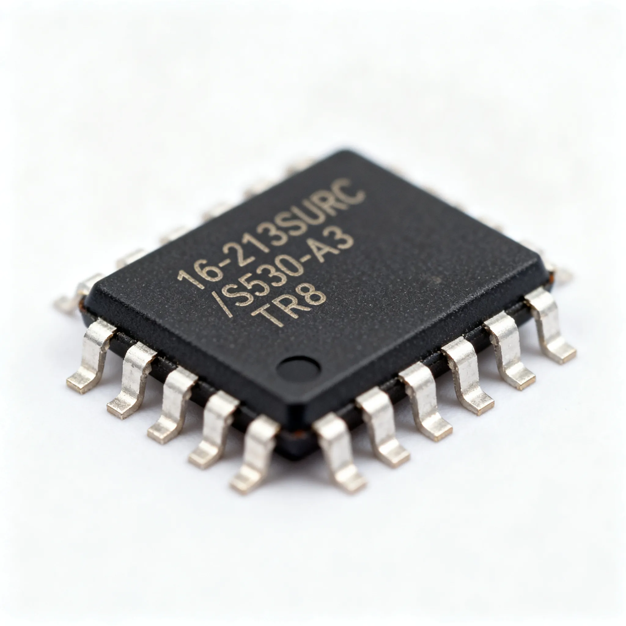
Space-constrained designs don't forgive poor component choices. When your PCB real estate shrinks to the size of a postage stamp—think Bluetooth trackers, hearables, glucose monitors, or dense industrial control panels—every square millimeter counts. The humble 0402 LED remains one of the most effective solutions for miniature status indication, and Everlight's 16-213SURC/S530-A3/TR8 has earned its place on thousands of BOMs worldwide.
This isn't just another commodity LED. The 16-213SURC/S530-A3/TR8 is a 1.0 mm × 0.5 mm surface-mount red LED with a water-clear lens, delivering 25–40 mcd of luminous intensity at a typical forward voltage of just 2.0 V. At 20 mA drive current, it provides crisp, visible red indication without the power penalty of larger packages. With LCSC alone listing 19,210 units from just $0.0182 (source), this part sits at the sweet spot of cost, availability, and proven field reliability.
Key Takeaways: The 16-213SURC/S530-A3/TR8 offers design teams a production-hardened 0402 red LED with datasheet-grounded specifications, intensity binning options from A2 through A6, and broad distributor coverage. Whether you're prototyping a new wearable or ramping volume production, understanding its datasheet and pinout details before tape-out saves costly re-spins.
Engineers gravitate toward this Everlight series for three practical reasons: consistent binning across production lots, a mature supply base that supports allocation-sensitive procurement, and a footprint shared across color variants—meaning you can swap red for green without touching the PCB layout. The following sections unpack every design and sourcing consideration you'll need.
Decoding the 16-213SURC/S530-A3/TR8 Datasheet: Electrical, Optical, and Pinout Details
Everlight's datasheet for the S530 series (Mouser specsheet) packs critical electro-optical parameters into a compact document, but engineers new to this LED family often need help decoding the suffixes, binning tables, and pad orientation details. Let's walk through what each datasheet section means for your design.
The part number breaks down systematically: 16-213 specifies the 0402 package outline (1.0 mm × 0.5 mm × 0.35 mm profile), SURC designates ultra-bright red with a water-clear lens, S530 identifies the chip platform and intensity binning scheme, A3 locks in the luminous intensity rank at 25–40 mcd, and /TR8 indicates tape-and-reel packaging with 8 mm carrier tape width.
The A3 suffix matters more than most engineers realize. Everlight offers intensity bins from A2 through A6, with each bin spanning roughly a 1.5x to 2x range in luminous intensity. A3 covers 25–40 mcd at IF = 20 mA. If your design demands tighter brightness uniformity across a panel of indicators, you'll want to specify a single bin (or adjacent bins) on your PO and verify with your distributor before committing to a production lot.
| Parameter | Value/Range | Unit/Notes |
|---|---|---|
| Package Type | 0402 (1.0 × 0.5 × 0.35 mm) | SMD, water-clear lens |
| Emitted Color | Red, peak λ = 631 nm | GaAlAs/GaAs chip technology |
| Forward Voltage (VF) Typ. | 2.0 V | At IF = 20 mA, Ta = 25°C |
| Forward Voltage (VF) Max. | 2.4 V | At IF = 20 mA |
| DC Forward Current Max. | 25 mA | Continuous operation |
| Peak Forward Current | 100 mA | Duty ≤ 1/10, pulse width ≤ 0.1 ms |
| Luminous Intensity (A3 Bin) | 25–40 mcd | IF = 20 mA, A3 rank per S530 table |
| Viewing Angle (2θ½) | 120° | Wide dispersion for indicator use |
| Reverse Voltage Max. | 5 V | Do not exceed in reverse bias |
| Power Dissipation | 95 mW | Absolute maximum rating |
| Operating Temperature | -40°C to +85°C | Industrial temperature range |
| Soldering Peak Temp. | 260°C | Reflow, per J-STD-020 profile |
The above figures come directly from Everlight's published specifications (Evelta datasheet cross-reference). Note that the absolute maximum ratings are just that—survival limits, not operating points. Running continuously at 25 mA leaves zero headroom; most conservative designs target 15–18 mA for long-term reliability, particularly in elevated-ambient enclosures where the 85°C upper limit can approach quickly.
Pinout and Pad Layout: Getting the Polarity Right
The 0402 LED package has no silkscreen-friendly markings on top—polarity identification happens from the bottom side. Everlight places a chamfered corner or a small dot on the lens side to mark the cathode. On the PCB footprint, the cathode pad typically connects to ground (or the low side of your drive circuit), while the anode connects to the current-limited supply rail.
This orientation detail trips up engineers accustomed to larger packages with visible polarity marks. Before committing your layout, cross-reference the mechanical drawing in the datasheet with the recommended land pattern. The pad spacing centers at approximately 0.65 mm pitch—tight enough that even minor solder mask registration errors can cause bridging if pads are oversized. Everlight specifies a nominal 0.5 mm × 0.5 mm pad size with 0.45 mm gap between pads for standard reflow profiles.
Tip: If you're integrating this LED into a mixed-technology board that also goes through selective wave soldering, orient the cathode pad consistently across all indicator positions. Random rotation creates assembly defects that QA catches late—and a batch of reversed-polarity LEDs on a production run is expensive to rework.
Comparing Color Options: 16-213SURC (Red) vs. 16-213SDRC (Green) in the Same 0402 Footprint
One of the most practical design advantages of Everlight's 16-213 platform is color-swappable footprints. The red 16-213SURC/S530-A3/TR8 and the green 16-213SDRC/S530-A3/TR8 share an identical package outline, pad geometry, and polarity convention (LCSC pinout diagram). This means you can change indicator color mid-design—or even offer product variants with different LED colors—without respinning the PCB.
But identical footprints don't mean identical electrical behavior. The green variant operates at a significantly higher forward voltage, and its perceived brightness at the same drive current differs due to the human eye's photopic response curve and the chip's radiometric output.
| Comparison Metric | 16-213SURC/S530-A3 (Red) | 16-213SDRC/S530-A3 (Green) | Selection Criteria & Design Impact |
|---|---|---|---|
| Peak Wavelength | 631 nm (typ.) | 520–535 nm (Utmel SDRC specs) | Red for alert/error states; green for status-OK / power-good; evaluate ambient light washout |
| Forward Voltage (VF Typ.) | 2.0 V | ~3.2 V | Higher VF in green means larger resistor voltage drop and different power budget; recalculate series resistors |
| Luminous Intensity (A3 Bin) | 25–40 mcd | Comparable binning structure | Perceived brightness differs; green appears brighter to the human eye at equal mcd—verify with prototype |
| Chip Technology | GaAlAs/GaAs | InGaN | Different degradation mechanisms; InGaN generally more robust at elevated temperature |
| Package / Footprint | 0402, 1.0 × 0.5 mm | 0402, 1.0 × 0.5 mm — identical | PCB reuse confirmed (pinout diagram); same land pattern, same cathode mark orientation |
The key takeaway: PCB layout reuse is a genuine advantage, but don't drop a green LED into a red LED's BOM line without recalculating the series resistor. A circuit designed for a 2.0 V VF at 20 mA with a 3.3 V rail uses a 65 Ω resistor. That same resistor with a 3.2 V green LED yields essentially zero current—and no light output. Recalculate for the target IF using (V_supply – VF)/IF, factoring in the driver's output impedance and any supply tolerance.
For designers building bi-color or RGB indicators, this family supports mixed placement on the same board with predictable assembly yields. The consistent 0402 outline means your pick-and-place nozzle and vision system settings transfer directly between color variants—no feeder recalibration needed.
Design and Sourcing Tips for the 16-213SURC/S530-A3/TR8 in Production
Getting the 16-213SURC/S530-A3/TR8 to perform reliably in production requires attention to a few practical details that datasheets often mention in footnotes but engineers sometimes overlook. Here's what to focus on across design, assembly, and procurement.
Current-Limiting Resistor Calculation
The standard approach works, but production variability demands margin. Using the typical VF of 2.0 V at 20 mA, calculate R = (V_supply – 2.0 V) / 0.020 A. However, VF can range from 1.8 V to 2.4 V across temperature and lot variation. If your supply rail has ±5% tolerance and VF hits the minimum 1.8 V, the current through your resistor can spike beyond the 25 mA absolute maximum—particularly at cold start when VF drops further.
Recommendation: Design for a nominal IF of 15 mA using the typical VF, then verify worst-case current using the minimum VF and maximum supply voltage. If the result exceeds 22 mA, increase the resistor value. This derating approach buys you margin against both supply variation and the LED's negative temperature coefficient of VF (roughly -2 mV/°C for GaAlAs).
Soldering and Assembly
The 16-213SURC/S530-A3/TR8 ships on 8 mm tape-and-reel with the cathode oriented toward the sprocket holes—a critical detail for pick-and-place programming. Verify orientation with your assembly house before the first run. The part tolerates standard lead-free reflow profiles peaking at 260°C, but Everlight recommends no more than two reflow cycles. If your board undergoes double-sided assembly plus rework, flag this LED as a single-pass component.
For hand-soldering in prototype or low-volume builds, use a fine-tip iron at ≤300°C with dwell time under 3 seconds. Preheat the board to 100–120°C if possible—thermal shock on these tiny packages can delaminate the lens epoxy before you even see the damage.
Intensity Binning and Procurement Discipline
One of the most common production headaches with this series stems from uncontrolled bin mixing. Everlight ships intensity ranks A2 through A6 for the SURC variant, spanning roughly 15 mcd to 89 mcd (per the S530 rank table). If your design uses multiple LEDs on the same panel—status indicators, backlight bars, or matrix displays—mixing an A2 and an A6 bin creates a visually obvious brightness step that end-users perceive as a defect.
Community designs illustrate how these LEDs scale in arrays: an 8×16 LED matrix using the A4 variant (EasyEDA module) demonstrates how consistent binning across 128 units makes or breaks the visual result. For matrix applications, specify adjacent bins (e.g., A3+A4) and request a single date-code lot.
Procurement checklist for production buyers:
- Specify the exact intensity bin (A3 for the 16-213SURC/S530-A3/TR8) on the PO, not just the base part number.
- Request a certificate of conformance (CoC) with lot-specific VF and IV test data—this becomes essential for ISO/medical device traceability.
- Clarify whether partial reels are acceptable; TR8 packaging typically ships in 4,000-piece reels, and partials may come from opened stock with compromised moisture sensitivity.
- For allocation-sensitive procurement, confirm current availability and lead time via RFQ rather than relying on cached distributor inventory figures.
- Verify the moisture sensitivity level (MSL)—these 0402 LEDs typically rate at MSL 3, requiring baking if floor life exceeds 168 hours after the sealed bag is opened.
| Design/Purchasing Consideration | What to Specify | Why It Matters |
|---|---|---|
| Current-Limiting Resistor | Derive at 15 mA nominal; verify ≤22 mA worst-case | Prevents overdrive at cold start and high-line conditions |
| PCB Land Pattern | 0.5 × 0.5 mm pads, 0.45 mm gap, per Everlight recommendation | Minimizes tombstoning and solder bridging in reflow |
| Reflow Cycles | Maximum 2 cycles; flag on assembly drawing | Excess heat degrades epoxy lens and bond wire integrity |
| Intensity Bin | A3 (25–40 mcd) or adjacent bins per design needs | Prevents visible brightness mismatch across multi-LED panels |
| Moisture Sensitivity | MSL 3; bake 24h at 60°C if floor life exceeded | Prevents popcorning during reflow on moisture-ingressed packages |
| Tape-and-Reel Orientation | Cathode toward sprocket holes per EIA-481 | Correct pick-and-place polarity; reversed parts are scrap after reflow |
| Distributor RFQ | Request lot-specific CoC and bin verification | Traceability for regulated industries; avoids bin mix surprises |
Treat these points as a design-for-manufacturing checklist, not afterthoughts. A 0402 LED costs pennies, but a field failure traced to solder joint fatigue or brightness mismatch can cost thousands in rework and brand damage.
16-213SURC/S530-A3/TR8: Pinout, Brightness, and Sourcing Questions Answered
Below are direct, practical answers to the questions engineers and procurement professionals ask most often about the 16-213SURC/S530-A3/TR8.
Q: What does the A3 suffix in 16-213SURC/S530-A3/TR8 mean?
The A3 suffix indicates the luminous intensity bin per Everlight's S530 ranking table. At IF = 20 mA and Ta = 25°C, the A3 bin covers 25–40 mcd. Other available bins include A2 (15–36 mcd), A4 (36–50 mcd), A5 (48–70 mcd), and A6 (58–89 mcd). The bin you choose should match the brightness uniformity requirements of your application. If you need consistent illumination across a panel of indicators, request a single bin on your PO and verify with your distributor that the entire lot falls within that rank. Bins are not interchangeable without visible brightness variation—a lesson many designers learn the hard way after receiving mixed-lot inventory.
Q: How do I identify the anode and cathode from the pinout?
Polarity identification for the 16-213SURC/S530-A3/TR8 relies on a bottom-side cathode mark. On the underside of the 0402 package, Everlight places either a chamfered corner or a small dot on the lens side—this denotes the cathode. The corresponding PCB pad connects to the low side of your drive circuit. The anode occupies the opposite pad and connects to the current-limited supply rail. Always cross-reference the mechanical drawing in Everlight's datasheet (specsheet here) before finalizing your footprint. A quick in-circuit verification technique: probe with a multimeter in diode mode; the LED will glow faintly when forward-biased, confirming orientation before reflow.
Q: What is the typical forward voltage and recommended operating current?
The typical forward voltage (VF) is 2.0 V at IF = 20 mA, with a maximum VF of 2.4 V across the operating temperature range. The absolute maximum DC forward current is 25 mA, but continuous operation at this level leaves no thermal headroom. Most designs target 15–18 mA for long-term reliability. Calculate the current-limiting resistor as R = (V_supply – VF) / IF. For multiplexed or PWM-driven applications, respect the peak current limit of 100 mA with a maximum 10% duty cycle and pulse width ≤ 0.1 ms. Exceeding these limits accelerates degradation of the GaAlAs die, particularly at elevated ambient temperatures approaching the 85°C upper limit.
Q: Can I substitute the 16-213SDRC/S530-A3/TR8 green LED without changing the PCB layout?
Yes—the green variant uses the identical 0402 footprint and cathode-mark polarity convention (verified by LCSC pinout diagram). However, two critical differences demand attention. First, the green LED's forward voltage rises to approximately 3.2 V, so you must recalculate the series resistor: a circuit optimized for the red LED's 2.0 V VF will severely under-drive (or fail to illuminate) the green variant. Second, perceived brightness differs due to the eye's photopic response—green appears brighter than red at equal photometric output. Prototype both variants in your actual enclosure and ambient lighting conditions before committing to a single resistor value for mixed-color BOMs.
Q: Where can I source the 16-213SURC/S530-A3/TR8 in volume?
LCSC maintains large stock levels—19,210 units as of their most recent update, with pricing starting under $0.02 per unit at volume quantities (LCSC listing). Authorized distributors including Mouser and Evelta also carry the series, and Everlight's global distribution network provides additional sourcing channels. When ordering in volume, confirm real-time inventory with your supplier, specify your intensity bin (A3 in this case), and request lot traceability documentation. For allocation-sensitive procurement, use an RFQ process to verify current availability and allocation-backed lead times—don't rely on cached website inventory figures for production planning.
Q: Is there a reliable alternative if this part is on allocation?
The most practical buffer-stock strategy leverages Everlight's own binning variants rather than seeking third-party alternatives. The 16-213SURC/S530-A3/TR8 belongs to a family that includes adjacent intensity bins (A2, A4, A5) and different color variants (SDRC green) in the identical 0402 footprint. Because the package, pinout, and land pattern are consistent across the series, qualifying an A4-bin red LED or an SDRC green LED as a contingency part is far simpler than sourcing a pin-compatible LED from another manufacturer—which rarely exists in this exact 0402 configuration with matching optical characteristics. If supply of the A3 bin tightens, evaluate A4 or A5 as near-equivalents, verify brightness compatibility in your application, and confirm allocation-backed lead times via RFQ.
References & Further Reading
- Everlight 16-213SURC/S530-XX/TR8 Electro-Optical Characteristics — Mouser Specsheet
- 16-213SURC/S530-A3/TR8 Product Detail — LCSC Electronics
- Everlight 16-213SDRC/S530-A3/TR8 Datasheet — Evelta (cross-reference for SURC series)
- Everlight 16-213SDRC/S530-A3/TR8 Pinout & Footprint Diagram — LCSC
- 16-213SDRC/S530-A3/TR8 Specifications — Utmel
- 8×16 LED Matrix using 16-213SURC/S530-A4/TR8 — EasyEDA Community Module
- IC-Online — RFQ and BOM Upload for Electronic Component Sourcing
The 16-213SURC/S530-A3/TR8 proves that even the most commoditized component category—0402 indicator LEDs—rewards engineers who read datasheets carefully and buyers who specify bins precisely. With a 2.0 V typical forward voltage, 25–40 mcd A3 intensity rank, and a proven 0402 footprint shared across the SURC/SDRC family, this Everlight LED fits seamlessly into designs ranging from single-indicator wearables to dense LED matrices. The real differentiator in production comes down to procurement discipline: locking in your intensity bin, verifying polarity on the assembly drawing, and derating drive current for thermal margin. If you're sourcing the 16-213SURC/S530-A3/TR8 for an upcoming production run—or qualifying it against alternate bins and colors—the fastest path to confirmed allocation and competitive pricing starts with an RFQ on IC-Online. Upload your BOM, specify your bin requirements, and let the platform match your line items to verified distributor inventory with the traceability your production demands.