

Tantalum Capacitor Polarity and Failure Analysis
You must understand the importance of capacitor polarity. Tantalum capacitors are polar capacitors. These electrolytic capac
You must understand the importance of capacitor polarity. Tantalum capacitors are polar capacitors. These electrolytic capacitors are a type of polar capacitor. Like other polarized capacitors, their orientation is critical. The tantalum capacitor polarity must be correct. You need to know what happens if polarity is reversed. A polar capacitor connected with reverse polarity will fail.
Safety Alert: Connecting this type of polar capacitor incorrectly causes catastrophic failure. This mistake creates a short-circuit. The capacitor will overheat rapidly. This can lead to smoke and fire. Always verify capacitor polarity. Proper handling of polarized capacitors, including these electrolytic capacitors and every polar capacitor, is essential for safety.
Key Takeaways
- Tantalum capacitors are polar. They must be connected the right way. Connecting them backward causes fire and damage.
- Check capacitor markings to find the positive (+) side. Look for a bar, a longer wire, or a plus symbol. The circuit board also has marks.
- Use a multimeter to check polarity if you are unsure. This helps you avoid mistakes before you solder.
- Too much voltage or ripple current can also break capacitors. Use a capacitor with a higher voltage rating than needed. This helps it last longer.
- Always check capacitor direction during assembly. This prevents failures and keeps your circuits safe.
How to Identify Capacitor Polarity
Correctly identifying capacitor polarity is a non-negotiable skill for any electronics work. A mistake here can be destructive. Fortunately, you can use several reliable polarity identification methods to ensure proper installation. You can learn how to identify capacitor polarity by examining the component itself, the circuit board, and by using test equipment for verification.
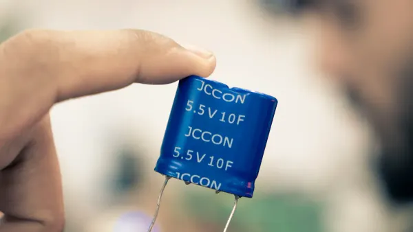
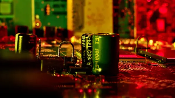
Tantalum Capacitor Markings
The first step is to inspect the capacitor itself. Manufacturers provide clear visual cues on the component's body. These tantalum capacitor markings vary between surface-mount (SMD) and through-hole packages.
-
Surface-Mount (SMD) Capacitors:
- Polarity Bar: You will find a distinct bar, stripe, or dash mark on the capacitor's body. This bar indicates the positive (+) terminal.
- Beveled Edge: Many molded chip tantalum capacitors also feature a beveled or angled edge. This bevel is also on the positive (+) side, often accompanying the polarity bar.
-
Through-Hole Capacitors:
- Longer Lead: For radial (standing) polar capacitors, one lead is longer than the other. The longer lead is the positive (+) anode.
- Plus Symbol: You will often see a
+symbol printed on the capacitor body. This mark is located next to the positive lead. These capacitor markings are very common. - Stripe/Arrow: On axial (inline) electrolytic capacitor markings, a stripe or arrow often points toward a specific terminal. For many electrolytic capacitor markings, this arrow points to the negative lead, but for some tantalum capacitor markings, it may indicate the positive pole. Always double-check the datasheet if you are unsure.
Tip: Never assume all capacitor markings are the same across different types. While these are common conventions for polar capacitors, always refer to the manufacturer's datasheet for absolute certainty.
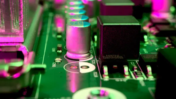
Reading PCB Silk Screen Indicators
The Printed Circuit Board (PCB) provides the next set of clues. The white layer of text and symbols on a PCB is called the silk screen. It contains essential capacitor polarity symbols and other pcb polarity marks.
You can identify the correct orientation using these common indicators:
- Plus Symbol (
+): The most common indicator is a+symbol printed on the PCB next to one of the pads. You must align the positive terminal of the capacitor with this mark. - Asymmetrical Pads: You may notice that the two pads for the capacitor are different shapes. Often, one pad is square or rectangular while the other is round. The rectangular pad typically indicates the positive (+) terminal.
- Other Symbols: While less common, some designs use alternative capacitor polarity symbols. You might see a thickened circle or a bold round line on the silk screen to mark the negative leg.
Critical polarized components, like tantalum capacitors, must be oriented correctly. The PCB silk screen should provide clear polarity marking that is visible for inspection. While industry standards like IPC suggest reserving space for such information, the specific symbols can vary between designers. Always pay close attention to these pcb polarity marks.
Verifying with a Multimeter
When in doubt, you should use a multimeter for final verification. This is the most reliable way to confirm tantalum capacitor polarity before soldering. Learning how to test a capacitor with a multimeter is a valuable skill. You can use either the resistance or diode test mode.
Using Resistance (Ω) Mode
This method works by observing the capacitor charge.
- Discharge the Capacitor: First, ensure the capacitor is fully discharged by shorting its leads together for a moment.
- Set the Multimeter: Switch your multimeter to a high resistance range, such as 200kΩ or higher.
- Connect the Probes: Place the red (positive) probe on one lead and the black (negative) probe on the other.
- Observe the Reading:
- If the probes are connected correctly (red to positive, black to negative), you will see the resistance value start low and climb steadily. It will eventually read "OL" (Over Limit) or "1" on a digital meter as the capacitor charges.
- If the probes are reversed, the reading may behave erratically or show a very low resistance.
- Confirm: The lead connected to the red probe when you see the steady rise in resistance is the positive (+) terminal. This process confirms both the capacitor's health and its polarity.
Using Diode Test Mode
This is a faster method for a quick check on how to test a capacitor with a multimeter.
- Set the Multimeter: Switch your multimeter to the diode test or continuity mode (often marked with a diode symbol).
- Connect the Probes: Touch the probes to the capacitor leads.
- Observe the Reading: If you see a brief value on the screen before it goes to "OL", the red probe is on the positive (+) terminal. If you see "OL" immediately, swap the probes. The correct orientation will show a momentary reading.
These polarity identification methods provide a complete toolkit for ensuring you install polarized capacitors correctly every time.
Understanding Tantalum Capacitor Polarity and Failure
Knowing how to identify capacitor markings is only half the battle. You must also understand why tantalum capacitor polarity is so important. The internal construction of these polar capacitors dictates their orientation. Understanding this design reveals why mistakes lead to such destructive failures. This knowledge helps you prevent circuit malfunction and ensure long-term reliability.
The Polarity of Tantalum Electrolytic Capacitors
The unique properties of these electrolytic capacitors begin with their construction. The anode (+) of a tantalum capacitor is made from a pellet of pure tantalum metal powder. This pellet is then put through an anodization process. This process grows an incredibly thin, uniform insulating layer of tantalum pentoxide over the entire surface of the tantalum. This layer is the capacitor's dielectric. The cathode (-) is typically a layer of solid manganese dioxide that makes contact with the dielectric.
The formation of the dielectric layer is what defines the polarity of tantalum electrolytic capacitors. The process happens in several stages:
- Tantalum powder is pressed into a pellet around a tantalum wire, which will become the anode lead.
- The pellet is heated in a vacuum at very high temperatures (1200–1800 °C). This fuses the powder particles together, creating a porous, sponge-like structure with a huge surface area.
- The dielectric layer is electrochemically grown on this surface. The thickness is precisely controlled by the voltage applied during this anodization step.
- A semiconducting oxide region forms between the tantalum metal and the tantalum pentoxide dielectric. This layer is the key. It allows current to flow easily in one direction but blocks it in the other. This one-way-gate characteristic is what makes these components polarized capacitors.
Failure from Reverse Polarity
So, what happens if polarity is reversed? Connecting these polar capacitors backward is one of the most common mistakes when using polar capacitors, and the result is immediate and violent. When you apply a reverse voltage, the dielectric layer's insulating properties break down. An electrochemical reaction begins to strip the oxide layer away, effectively destroying the capacitor's one-way gate.
This breakdown creates a low-resistance path, turning the capacitor into a short circuit. Current rushes through the component, causing rapid self-heating. This thermal runaway can happen incredibly fast. In some cases, a reverse-biased tantalum capacitor can fail in as little as three seconds.
Failure Symptoms: The signs of a reverse polarity failure are unmistakable and dangerous. These bad capacitor symptoms are severe capacitor failure signs.
- Rapid Overheating: The capacitor body becomes extremely hot to the touch almost instantly.
- Charring and Smoke: The component will quickly begin to char, discolor, and release acrid smoke.
- Ignition: In many cases, the capacitor will ignite, creating a small but intense flame that can damage nearby components and the PCB itself.
You must always double-check capacitor polarity before applying power. The consequences of a mistake are too severe to ignore.
Failure from Overvoltage and Ripple Current
Beyond reverse polarity, two other conditions can cause these electrolytic capacitors to fail: overvoltage and excessive ripple current. While sometimes less dramatic than a reverse polarity event, these failures are just as destructive to your circuit.
Overvoltage Failure An overvoltage event occurs when the voltage applied to the capacitor exceeds its rated voltage. Voltage spikes can physically puncture the delicate tantalum pentoxide dielectric layer. This damage creates a microscopic fault site.
- High leakage current begins to flow through this compromised point.
- This current generates localized heat.
- The heat can lead to thermal runaway, causing a short circuit and showing bad capacitor symptoms similar to a reverse polarity failure.
Ripple Current Failure In many circuits, a capacitor must handle both DC voltage and a fluctuating AC component, known as ripple current. This ripple current causes the capacitor to constantly charge and discharge, which generates internal heat. The power dissipated as heat is calculated as I²R, where 'I' is the ripple current and 'R' is the capacitor's Equivalent Series Resistance (ESR).
If the ripple current is too high, the capacitor cannot shed the heat fast enough. This self-heating raises the component's internal temperature, which can degrade the dielectric, increase leakage current, and eventually lead to thermal runaway and failure. These symptoms can develop over time, leading to a latent failure that is difficult to diagnose.
Best Practice: Voltage Derating To prevent these failures, you must follow a critical design rule: voltage derating. For high-reliability applications, you should operate solid tantalum capacitors at 50% of their rated voltage. For example, if your circuit runs at 12V, you should select a capacitor with a voltage rating of 24V or higher. This safety margin protects the capacitor from unexpected voltage spikes and reduces stress, dramatically increasing the lifespan and reliability of your product. For complex designs involving high ripple currents, partnering with experts like Nova Technology Company (HK) Limited, a HiSilicon-designated solutions partner, can help ensure robust and reliable component selection.
Correctly managing voltage and ripple current is just as important as observing the correct capacitor polarity for these polarized capacitors.
Prevention and Best Practices
You can prevent most capacitor failures with careful planning and strict process controls. Understanding the risks during assembly and making smart design choices are your best lines of defense. These best practices ensure the long-term reliability of your electronic circuits.
Assembly and Rework Risks
The manufacturing floor is where many problems begin. Both automated and manual assembly processes introduce significant risks for polarized capacitors. One of the most common mistakes when using polar capacitors is incorrect orientation during placement. Even automated Surface Mount Technology (SMT) assembly is not foolproof.
Common automated assembly issues include:
- Machine Calibration: A misaligned pick-and-place nozzle or vision system can easily place a capacitor backward.
- Component Feeders: Improperly loaded tape-and-reel packaging can cause the machine to pick up the component incorrectly.
- Board Design: Poorly placed fiducial marks or inadequate spacing between components can confuse the assembly machine.
Manual assembly and rework carry even higher risks due to human error. To combat these issues, you must implement verification steps. Modern assembly lines use Automated Optical Inspection (AOI) systems. These machines can perform polarity verification, checking the orientation of each capacitor to ensure it matches the design. An AOI check is a critical quality gate in any high-reliability assembly process.
Design and Component Selection Guidelines
Your design choices have the biggest impact on reliability. Selecting the right capacitor and implementing proper design rules are essential. This is especially true when you decide when to use polar capacitors in demanding applications.
Safer by Design: Polymer Capacitors For applications where ignition risk is a major concern, you should consider using polymer tantalum polar capacitors. Unlike traditional Manganese Dioxide (MnO2) types, polymer polar capacitors do not fail with a flame or explosion. They typically fail into a resistive state, preventing catastrophic damage.
Your most important tool is voltage derating. You should operate a capacitor well below its maximum rated voltage.
- High-Reliability: Use a 50% derating. For a 12V circuit, select a 24V or 25V capacitor.
- Low-Impedance Circuits: Use a more aggressive derating of 66% (operate at 1/3 of rated voltage). Low circuit impedance allows high inrush currents that can destroy a capacitor, so this extra margin is crucial.
Finally, you must account for ripple current. High ripple current generates internal heat, which can lead to thermal breakdown. For complex designs involving low impedance or high ripple current, partnering with an expert like Nova Technology Company (HK) Limited, a HiSilicon-designated solutions partner, can help you make robust component selections. Proper capacitor selection is a cornerstone of reliable product design. Knowing when to use polar capacitors and how to select them correctly prevents failures before they happen.
You must master tantalum capacitor polarity for circuit safety. Correct capacitor polarity is non-negotiable for all polarized capacitors and polar capacitors. A mistake with these electrolytic capacitors causes destructive failure, while overvoltage can also destroy a capacitor.
Key Takeaways for Reliability
- Design: Always derate the voltage for every capacitor.
- Assembly: Your assembly process must verify orientation.
- Handling: All polar capacitors, including these polarized capacitors and electrolytic capacitors, demand careful handling during assembly. A bad capacitor can ruin a board. This careful assembly and a robust final assembly check prevent failures for all polar capacitors.
FAQ
What happens if I install a tantalum capacitor backward?
You will cause immediate and catastrophic failure. A reverse-biased tantalum capacitor creates a short circuit. This leads to rapid overheating, smoke, and a potential fire. You must always verify the polarity before applying power to the circuit.
Why is voltage derating so important for tantalums?
Voltage derating provides a crucial safety margin. It protects the capacitor from voltage spikes that can puncture its delicate dielectric layer. Operating at 50% of the rated voltage significantly reduces stress, prevents thermal runaway, and dramatically increases the component's lifespan and reliability.
Can I replace a regular electrolytic with a tantalum capacitor?
You can sometimes make this substitution, but you must be careful. Tantalum capacitors have lower ESR and are less tolerant of overvoltage and ripple current. You should always check the circuit's requirements and apply proper voltage derating before making a swap.
Do all tantalum capacitors ignite when they fail?
No. Traditional manganese dioxide (MnO2) tantalum capacitors can ignite. However, you can choose polymer tantalum types for safer failure modes. Polymer capacitors typically fail into a high-resistance state without smoke or flame, making them ideal for high-reliability applications where ignition is a concern.


