Why EVAP Control System Leak Is Actually an Electronic Failure
An evap control system leak code often stems from electronic sensor drift, corroded wiring, or solenoid circuit faults misinterpreting pressure signals.
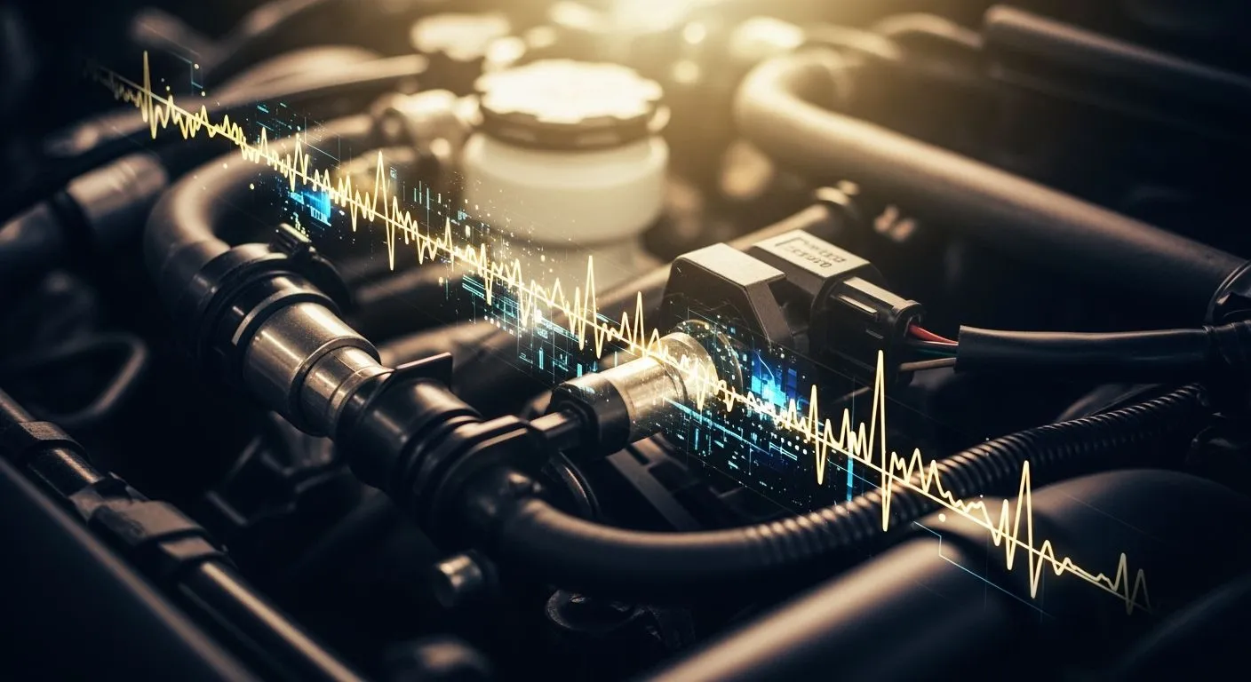
You inspect the rubber hoses and tighten the gas cap on your vehicle. Yet, the onboard computer still displays an evap control system leak error code. Why does this false leak flag appear without physical damage? Modern engine control units track vapor pressure using electronic sensors, vent solenoids, and software algorithms. A tiny signal glitch or a failing driver circuit triggers a leak warning instantly. The control module misinterprets electrical sensor drift as an actual physical leak. You must check electronic components before replacing a sealed gas cap or intact lines. Isolating solenoid coil resistance and voltage drop issues saves time during diagnostic testing.
Key Takeaways
- Modern car computers track fuel vapor pressure using electronic sensors and software algorithms.
- Corroded wires and sensor glitches create false leak codes on your car dashboard.
- Faulty valve solenoids fail to seal properly and confuse the engine control unit.
- A multimeter helps test electrical circuit resistance before you replace intact fuel hoses.
- Check electronic sensor signals first to save valuable time and repair money.
Electronic Architecture Behind EVAP Control System Leak

Modern vehicles manage fuel vapor through a precise evaporative emission control system network. The engine control unit relies on dedicated electronic components to monitor pressure and regulate vapor flow. Nova Technology Company (HK) Limited, a HiSilicon-designated solutions partner, provides advanced chip-level solutions and microcontrollers that process these automotive electronic control unit signals.
| Component | Role in leak detection | Signal interaction |
|---|---|---|
| Canister purge solenoid (CPS) | Normally closed solenoid separating the engine from the vapor system | PCM duty-cycle controls it; when opened, intake manifold vacuum pulls vapors and creates test vacuum |
| Canister vent solenoid (CVS) | Normally open solenoid that seals the vapor system for leak integrity checks | PCM closes it to isolate the system so pressure changes can be detected |
| Fuel tank pressure sensor (FTPS) | Measures small pressure changes in the vapor system, displayed in inches of water | Three-wire pressure transducer sends a voltage signal to the PCM; PCM uses the signal to validate CPS/CVS operation and determine if leaks exist |
Function of Purge and Vent Solenoids
The engine control unit executes automated diagnostic routines using these electronic actuators. The system completes a specific sequence during a leak test:
- The PCM closes the vent valve to seal the EVAP system from atmosphere.
- The PCM opens the purge valve to apply engine vacuum, or commands a pump to pressurize the sealed system.
- After the target vacuum/pressure is reached, the PCM closes the purge valve and uses the fuel tank pressure sensor to monitor whether the pressure/vacuum holds or decays.
- Holding pressure/vacuum indicates a sealed system; decay indicates a leak. The decay rate distinguishes a large leak (P0455), small leak (P0442), or very small leak (P0456).
- The source describes the purge valve as open/closed rather than an explicit duty cycle, so the duty-cycle evidence is limited to these commanded states.
Proper solenoid operation prevents vapor escape while maintaining correct system pressure. A stuck valve disrupts this delicate equilibrium immediately.
How Signal Glitches Mimic Physical Leaks
Electrical faults often confuse the control module into setting diagnostic trouble codes. Corroded wiring or unstable sensor voltages generate false failure flags.
| Code | Electrical circuit/sensor-signal fault indicated |
|---|---|
| P0443 | EVAP purge control valve circuit electrical fault |
| P0446 | EVAP vent control circuit malfunction |
| P0450 | Fuel tank pressure sensor general malfunction |
| P0452 | Fuel tank pressure sensor low input |
The word 'circuit' in a code such as P0446 can easily be misunderstood as an electrical fault, but in the cited case the charcoal canister was restricted due to contamination, meaning the electrical circuit was actually working correctly.
Voltage fluctuations mimic actual pressure drops inside the tank. You might diagnose an evap control system leak, yet the actual vapor seal remains completely airtight.
Electronic Failure Modes in Valve Circuits
Mechanical parts cause true vapor loss inside your vehicle emission network. Loose gas cap seals, cracked rubber hoses, and worn canister seals allow fuel vapors to escape into the atmosphere. However, electronic glitches often generate identical system warnings without a physical vapor leak. An internal electrical fault tricks the control module into setting persistent diagnostic trouble codes during normal vehicle operation. Electronic valve sticking and coil resistance changes fool the system completely. You might replace a good gas cap or intact vacuum lines needlessly when an electrical component fails internally.
Purge and Vent Valve Defect Dynamics
The engine control module depends on precise mechanical responses from solenoids during automatic testing routines. Mechanical sticking or internal coil breakdown disrupts these routine leak tests. Intermittent valve failures alter circuit current and prevent proper valve sealing during operation. Consequently, the control unit misinterprets this electrical behavior as a true vapor leak inside the fuel system.
| Electronic failure mode | Evidence summary |
|---|---|
| Solenoid failure | The purge valve solenoid may stick open or closed when it fails to actuate in response to the ECM signal. |
| Faulty/damaged wiring | Worn or damaged wiring can interrupt or block ECM communication with the purge valve solenoid. |
| P0443 purge control valve circuit fault | The purge control valve circuit is not performing as expected; loose connections or damaged wires are cited causes. |
A stuck purge valve allows intake vacuum to pull vapor at the wrong moment during driving, simulating a system leak. Conversely, a failing vent valve prevents the system from sealing properly during test execution. Wiring issues like chafed insulation or damaged connector pins interrupt crucial control signals. The system cannot hold vacuum or pressure during automated checks. The computer assumes a physical leak exists across the network when the circuit breaks down.
| Code/Fault | Evidence summary |
|---|---|
| P0498 EVAP vent valve control circuit low | A low circuit condition in the vent solenoid; the most common cause is EVAP vent valve failure, while wiring problems (broken/chafed wires, harness issues, connector pin damage) are also common. |
| P0499 EVAP vent valve control circuit high | A high circuit condition in the vent solenoid; causes mirror P0498, generally vent valve failure or wiring/harness/connector issues. |
Sensor Drift and Voltage Drops
Pressure sensor signal accuracy determines whether the engine module flags a vapor leak correctly. The fuel tank pressure sensor converts tiny pressure changes into specific voltage outputs for the module. Tiny voltage drops corrupt this critical communication link over time. Corroded ground wires, loose terminals, or aged sensor elements alter baseline voltage readings slowly during vehicle operation.
The control module records signal shift as a sudden change in vapor pressure. That false reading triggers generic p04xx codes immediately. You might tighten your gas cap repeatedly to clear the check engine light. However, the system continues reporting an evap control system leak because the raw voltage remains incorrect.
Electrical resistance creates false signals without physical seal failure anywhere in the system. Corroded harness pins produce a voltage drop across the sensor circuit. The engine computer monitors the signal drift and misinterprets the electrical drop as a pressure leak. A single faulty dtc flag appears on your diagnostic tool while the tank remains fully sealed. Isolating circuit continuity and sensor voltage prevents unnecessary mechanical component replacements on your vehicle.
Troubleshooting EVAP System Signal and Hardware Faults
OBD-II Live Data and Circuit Resistance Checks
You must start troubleshooting evap system problems by connecting an OBD-II scan tool to view live sensor data. Observe the fuel tank pressure sensor voltage while commanding the vent solenoid closed and the purge solenoid open. An immediate pressure drop indicates proper mechanical seal integrity. However, erratic voltage readings or delayed solenoid responses point directly to circuit faults rather than a physical vapor leak. Engine modules flag p04xx codes when these sensor signal variations mimic a small vapor leak during active self-tests.
Next, disconnect the wiring harness to test valve solenoid coil resistance using a digital multimeter. Measure the ground circuit voltage drop while operating the actuators under actual vehicle load conditions. High electrical resistance across corroded connector pins reduces operating current, causing partial solenoid opening during testing. This subtle electrical failure triggers an active dtc leak code even when all rubber lines remain fully intact.
Smoke Testing vs. Electrical Verification
Technicians often introduce artificial smoke into vapor lines to find evap leak sources visually. Smoke testing reveals cracked canisters, deteriorated hoses, and loose gas caps quickly. However, smoke testing cannot identify dynamic solenoid duty-cycle failures or corrupted signal voltages. A stuck vent solenoid creates an internal vapor leak state, but you might mistakenly replace a good valve without verifying its driver circuit signal first.
- Verify supply voltage and control circuit ground integrity using a digital multimeter.
- Monitor real-time sensor voltage changes using OBD-II live data scanner commands.
- Introduce low-pressure smoke to find evap leak pinholes across physical rubber lines.
You streamline your diagnostic workflow by isolating electrical components before performing mechanical pressure tests. Correcting underlying signal drift eliminates false leak flags and system leak warnings instantly. Checking circuit integrity first prevents unnecessary hose replacements during troubleshooting evap system errors on modern vehicles.
Electronic valve defects and sensor signal drift regularly mask themselves as mechanical vapor issues. You often see a persistent evap control system leak code even when your rubber hoses remain completely intact.
You must adopt an updated diagnostic workflow to resolve these issues efficiently. First, verify circuit continuity, terminal voltage, and live data using a multimeter and scan tool. Next, perform a physical smoke test to check for a small vapor leak across the sealed fuel lines.
Treating active EVAP leak codes as electrical diagnostic tasks saves valuable repair time. You easily prevent unnecessary hose replacements by testing valve solenoids and control circuits first.
FAQ
Can a loose gas cap cause an electronic error code?
Yes. A loose gas cap allows fuel vapor to escape. The engine control module detects the resulting pressure drop. It sets p04xx codes to warn you about the system issue.
Why does the engine computer report a leak when my gas cap is tight?
Your vehicle relies on solenoids and pressure sensors. Damaged wiring or corroded sensor pins create signal glitches. The control unit misinterprets these electrical drops as an actual vapor leak, even with a sealed gas cap.
How do I know if the gas cap or an electrical circuit failed?
You can inspect the rubber seal on your gas cap first. Then, use a multimeter to measure solenoid coil resistance and check sensor voltage. Live data checks reveal electrical faults that mimic a physical leak.
Will clearing the dtc fix my vehicle issue permanently?
Clearing the dtc simply turns off your check engine light temporarily. The computer retests the system during your next drive. You must repair underlying electrical faults or mechanical issues to prevent the error from returning.