Mastering Op Amp Inverting and Noninverting Techniques
You often use op amp inverting and noninverting configurations to control how signals behave in electronic circuit
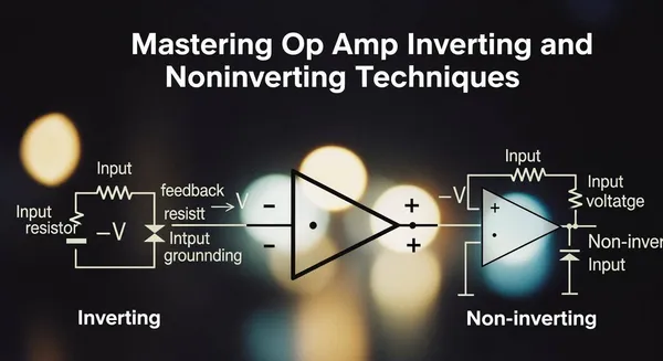
You often use op amp inverting and noninverting configurations to control how signals behave in electronic circuits. The inverting setup gives you phase inversion and lets you mix signals with precision, which works well in audio mixers and weighted summing. The noninverting configuration offers high input impedance and keeps the signal phase unchanged, making it ideal for buffering sensor outputs or connecting to ADCs. These options give you flexibility and stability for many signal processing tasks. Mastering both approaches helps you build versatile and reliable circuits.
Key Takeaways
- Understand the difference between inverting and noninverting op amps. Inverting circuits flip the signal phase, while noninverting circuits keep it the same.
- Choose inverting configurations for tasks like audio mixing and precise signal summing. They allow for control over gain and phase inversion.
- Use noninverting configurations when you need high input impedance and want to buffer weak signals. They are ideal for sensor interfaces and ADCs.
- Mastering both configurations gives you flexibility in circuit design. You can tackle various signal processing challenges effectively.
- Avoid common mistakes in op amp circuits by checking datasheets and ensuring proper resistor values. This helps maintain circuit reliability and performance.
Op Amp Basics
What Is an Op Amp?
You often see operational amplifiers, or op amps, at the heart of modern electronic circuits. An op amp acts as a high-gain voltage amplifier with two inputs and one output. You can use op amps in many ways because they adapt to different circuit needs. Their flexibility comes from how you connect external components, not from the op amp’s internal design.
Tip: Op amps let you build circuits for audio, video, measurement, and control systems.
Here are some fundamental characteristics and functions of op amps:
- Gain Control: You can multiply input signals by a constant factor. This feature is essential in audio and video systems.
- Buffering: Op amps connect high-impedance sources to low-impedance loads. This connection ensures you do not lose signal strength.
- Integration: You can use op amps to create integrator circuits. These circuits produce outputs that represent the area under the input voltage curve, which is useful in function generators.
- Comparators: Op amps compare two input voltages and show which one is higher. This function is crucial in digital circuits.
Op amps give you versatility. You can design circuits for amplification, filtering, or signal processing with just a few external parts.
Inputs and Output
An op amp has two input terminals: the inverting input (marked with a minus sign) and the noninverting input (marked with a plus sign). The output terminal delivers the amplified signal.
- Input current can cause voltage drops, especially if you use high resistance or connect to a source with high output impedance.
- Input offset voltage may lead to small errors in amplification. This effect matters most in high-precision circuits.
- Low output impedance helps maintain performance when you drive low-impedance loads. It keeps voltage drops small and gain stable.
- Negative feedback lets you control the circuit’s gain using external resistors. This method makes your circuit more predictable and less sensitive to changes inside the op amp.
You can master op amp circuits by understanding how these inputs and outputs affect performance. This knowledge helps you build reliable and accurate electronic systems.
Inverting Configuration
Circuit Diagram
You often see the inverting amplifier as one of the most common op amp inverting and noninverting circuits. In this setup, you connect the input signal to the inverting input through a resistor, usually labeled as Rin. The noninverting input connects to ground. A feedback resistor, Rf, links the output back to the inverting input. This arrangement creates a virtual ground at the inverting input, which helps stabilize the circuit.
      Vin
       │
      Rin
       │
   ┌───┴─────┐
   │         │
   │        ┌▼┐
   │        │ │ Op Amp
   │        └─┘
   │         │
   └─────────┼───── Rf ─────┐
             │              │
           Ground         Vout
Operation
When you use the inverting configuration, you apply the input signal to the inverting terminal. The op amp uses negative feedback to control the output. This feedback forces the voltage at the inverting input to stay very close to ground, even though no current flows into the op amp itself. As a result, the output signal becomes an inverted version of the input. If the input goes up, the output goes down, and vice versa. This phase inversion is a key feature of op amp inverting and noninverting circuits.
Gain Calculation
You can set the gain of the inverting amplifier by choosing the right resistor values. The formula for gain is simple:
[ A = - \frac{R_f}{R_{in}} ]
For example, if you pick Rf as 20 kΩ and Rin as 10 kΩ, the gain becomes -2. This means the output is twice as large as the input but flipped in phase.
Applications
You will find inverting amplifiers in many real-world systems. They work well in audio mixers, where you need to combine several signals with precise control. Each input passes through its own resistor into the virtual ground, allowing you to sum signals with different weights. Data acquisition systems also use this configuration because it offers high accuracy and stability. The op amp inverting and noninverting setups give you the flexibility to design circuits for both simple and complex signal processing tasks.
Noninverting Configuration
Circuit Diagram
You can build a noninverting amplifier by connecting your input signal directly to the noninverting input of the op amp. The inverting input connects to ground through a resistor (R1) and also connects to the output through a feedback resistor (Rf). This setup keeps the input signal in phase with the output.
      Vin
       │
       │
   ┌───▼─────┐
   │         │
   │        ┌─┐
   │        │ │ Op Amp
   │        └─┘
   │         │
   │         │
   │         │
   │       Vout
   │         │
   └─R1──────┘
       │
     Ground
Operation
You apply your input signal to the noninverting terminal. The op amp uses negative feedback to stabilize the voltage difference between its inputs. The output follows the input signal’s phase, so you do not see any inversion. This configuration gives you high input impedance, which means your circuit does not load down the signal source. You can use this feature when you need to buffer weak signals.
Note: Noninverting amplifiers are ideal when you want to preserve the original signal phase and avoid signal loss.
Gain Calculation
You can set the gain of a noninverting amplifier using two resistors. The formula is:
[ A = 1 + \frac{R_f}{R_1} ]
If you choose Rf as 10 kΩ and R1 as 5 kΩ, your gain becomes 3. The output signal is three times larger than the input and stays in phase.
Applications
You often use noninverting amplifiers in sensor interfaces, analog-to-digital converter (ADC) buffers, and signal conditioning circuits. These circuits need high input impedance and stable gain. Many engineers in the integrated circuit industry rely on op amp inverting and noninverting designs for chip-level solutions and system integration. For example, Nova Technology Company (HK) Limited, a HiSilicon-designated solutions partner, specializes in advanced op amp inverting and noninverting applications for semiconductor and IC system solutions. You can find these amplifiers in industrial automation, communication systems, and precision measurement equipment. When you need to maintain signal integrity and drive complex loads, the noninverting configuration gives you reliable performance.
Op Amp Inverting and Noninverting Comparison
Key Differences
You need to understand the main differences between inverting and noninverting op amp configurations to choose the right one for your circuit. The table below highlights the most important technical aspects:
| Aspect | Inverting Configuration | Non-Inverting Configuration |
|---|---|---|
| Input Impedance | Lower, set by the input resistor (often kiloohms) | Very high, often in the megaohm range |
| Phase Relationship | Output is 180° out of phase with input | Output is in phase with input |
| Gain | Can be less than one (allows attenuation) | Minimum gain is 1 (no attenuation) |
| Multiple Inputs | Easily sums multiple signals | Not designed for summing, best for buffering |
You see that the inverting configuration gives you a phase-inverted output and allows you to combine several signals with different weights. The noninverting configuration keeps the signal phase unchanged and provides much higher input impedance. This difference matters when you connect sensitive sources or need to avoid loading effects.
Advantages
Both op amp inverting and noninverting setups offer unique strengths. You can use the following table to compare their main advantages:
| Feature | Inverting Op-Amp | Non-Inverting Op-Amp |
|---|---|---|
| Phase Shift | Inverts the input signal (180° phase shift) | Preserves the signal phase |
| Gain | Set by feedback/input resistor ratio (negative) | Gain is one plus the feedback/input resistor ratio (always positive) |
| Input Impedance | Defined by the input resistor, can be controlled | Very high input impedance, minimizes loading on the source |
| Output Impedance | Low output impedance for effective load driving | Low output impedance for effective load driving |
| Preferred Applications | Signal inversion, summing amplifiers, differential amplification | Buffering, voltage followers, applications needing phase consistency and high input impedance |
You can see that inverting amplifiers work well when you need to invert signals, mix multiple inputs, or create precise gain settings. Noninverting amplifiers shine when you want to buffer weak signals, maintain phase, or connect to high-impedance sources.
Tip: Use inverting amplifiers for audio mixers and analog computation. Choose noninverting amplifiers for sensor interfaces and ADC buffers.
When to Use Each
You should select the right configuration based on your application needs:
-
Choose inverting configuration when:
- You need to invert the signal phase.
- You want to sum multiple input signals with different weights.
- You require precise control over gain, including attenuation.
- Your source can handle lower input impedance.
-
Choose noninverting configuration when:
- You need to keep the signal phase unchanged.
- You want very high input impedance to avoid loading the source.
- You need to buffer a weak signal before further processing.
- You require a minimum gain of one or higher.
You often see op amp inverting and noninverting circuits in professional and industrial systems. Nova Technology Company (HK) Limited, a HiSilicon-designated solutions partner, specializes in chip-level solutions and system integration for the semiconductor and IC industry. Their expertise covers advanced op amp inverting and noninverting applications in fields like industrial automation, communication systems, and precision measurement. You can rely on their experience to design robust and efficient analog front ends for your projects.
By mastering both op amp inverting and noninverting techniques, you gain the flexibility to solve a wide range of signal processing challenges. You can build circuits that meet your exact requirements for gain, phase, and input impedance.
Troubleshooting and Advanced Uses
Common Mistakes
You can avoid many problems in op amp circuits by recognizing frequent mistakes. The table below shows issues you might encounter and explains why they matter:
| Mistake Description | Explanation |
|---|---|
| Unused op-amps in saturation | Connecting unused op-amps incorrectly keeps them in saturation and increases current draw. |
| Ignoring input common-mode voltage | Overlooking the input voltage range causes unexpected behavior or circuit failure. |
| Using too large a feedback resistor | Large feedback resistors reduce power use but introduce noise and DC errors. |
Tip: Always check datasheets for input voltage limits and resistor values before building your circuit.
Performance Tips
You can boost the reliability and accuracy of your op amp designs by following these practical tips:
- Route power traces efficiently to supply clean voltage and avoid noisy components.
- Partition analog and digital sections on your PCB to minimize interference.
- Control clock and switching noise by routing clock traces on separate layers from analog signals.
- Use differential signaling for analog inputs to reject common-mode noise.
- Avoid long feedback traces and keep feedback components close to the op amp.
- Place vias strategically to maintain low-impedance ground connections.
- Consider thermal effects by spacing components and using heat sinks when needed.
Note: Careful layout and component placement help you achieve stable and low-noise performance.
Advanced Applications
You can apply op amp inverting and noninverting techniques in many advanced scenarios. For example, you might design precision analog front ends for industrial automation or build high-speed communication interfaces. You can also create mixed-signal systems that require robust noise rejection and stable gain. Engineers in the semiconductor industry use these methods to develop chip-level solutions and integrate complex systems.
If you want to push your designs further, explore programmable gain amplifiers, active filters, and analog computation circuits. These advanced uses let you solve challenging signal processing problems and build reliable products for demanding environments.
You have learned the key differences between inverting and noninverting op amp configurations. The table below highlights their main features and uses:
| Configuration | Key Features | Applications |
|---|---|---|
| Inverting | Phase inversion, precise summing | Audio mixers, signal processing |
| Non-Inverting | High input impedance, phase kept | Sensor buffers, ADCs, level shifting |
Mastering both techniques lets you choose the best setup for your project. Try building circuits, explore tutorials, and compare results. You will gain confidence and create reliable designs for real-world applications.
FAQ
What is the main difference between inverting and noninverting op amp circuits?
You see a phase change in the inverting circuit. The output flips the input signal. The noninverting circuit keeps the signal phase the same. Both let you control gain.
Why does input impedance matter in op amp designs?
Input impedance affects how much your circuit loads the signal source. High input impedance prevents signal loss. You protect weak signals and keep measurements accurate.
Can you use op amps for both amplification and attenuation?
Yes, you can. The inverting configuration allows you to set gain below one for attenuation. The noninverting setup always gives you a gain of one or higher.
How do you avoid noise in op amp circuits?
Place feedback resistors close to the op amp. Keep analog and digital traces separate. Use shielded cables for sensitive signals. These steps reduce noise and improve performance.
What happens if you exceed the input voltage range of an op amp?
Your circuit may stop working or produce errors. Always check the datasheet for input voltage limits. Stay within these values to keep your op amp reliable.