MOSFET vs IGBT: Key Considerations for Effective Power Electronics Design
Expert guide on MOSFET vs IGBT: Key Considerations for Effective Power Electronics Design. Technical specs, applications, sourcing tips for engineers and buyers.
Introduction
In the rapidly evolving field of power electronics, understanding the nuances between different semiconductor devices is crucial for engineers and designers. Metal-Oxide-Semiconductor Field-Effect Transistors (MOSFETs) and Insulated Gate Bipolar Transistors (IGBTs) are two pivotal components in power electronics design, each with unique characteristics and applications. With the global semiconductor market projected to reach $595.2 billion by 2026, as reported by the Semiconductor Industry Association, the demand for efficient and effective power electronics components has never been higher. This article delves into the technical specifications, design considerations, and application circuits of MOSFETs and IGBTs, providing a comprehensive guide for selecting the right component for your design.
Technical Overview
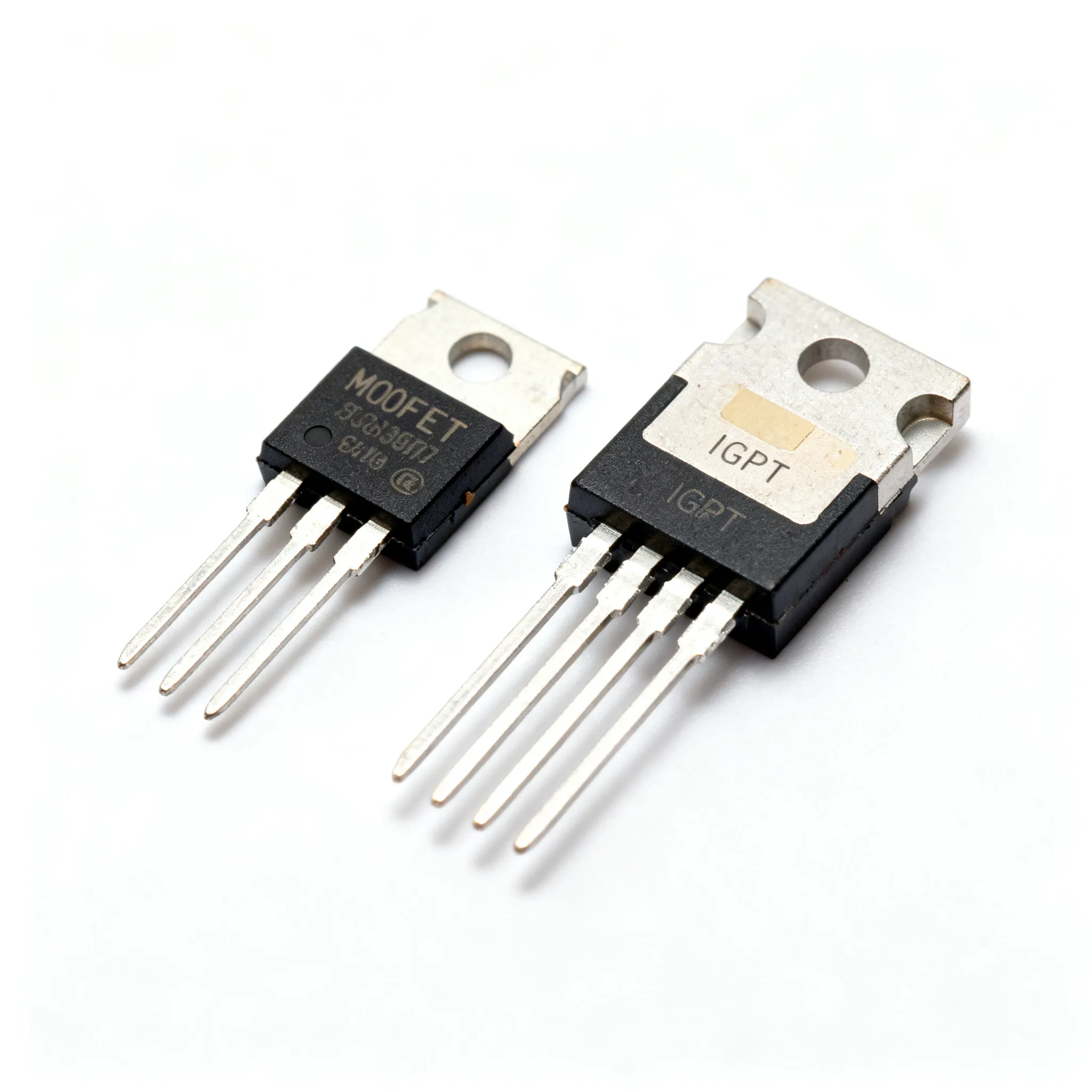
MOSFETs and IGBTs serve as switching devices in various power electronics applications, such as motor drives, power supplies, and inverters. A MOSFET is a voltage-controlled device, characterized by its fast switching speed and high efficiency at low voltages. It operates by varying the voltage at the gate terminal to control the current flow between the source and drain. MOSFETs are typically used in applications where speed and efficiency are critical, such as in low-voltage power supplies and DC-DC converters.
On the other hand, IGBTs combine the high-current capability of bipolar transistors with the ease of control of MOSFETs. They are used in high-power applications due to their ability to handle large currents and high voltages. IGBTs are preferred in applications like motor drives and high-voltage power inverters where efficiency and robustness are paramount. The choice between a MOSFET and an IGBT depends on several factors, including the application's voltage, current requirements, switching frequency, and thermal performance.
Detailed Specifications
| Parameter | MOSFET | IGBT | Units | Notes |
|---|---|---|---|---|
| Voltage Rating | 20V - 600V | 300V - 1200V | Volts | Varies with application |
| Current Rating | 1A - 200A | 10A - 300A | Amperes | Subject to package type |
| Switching Frequency | Up to 1 MHz | Up to 20 kHz | Hertz | Higher for MOSFETs |
| On-State Voltage Drop | 0.1V - 1V | 2V - 4V | Volts | Lower in MOSFETs |
| Gate Charge | 5 nC - 200 nC | 10 nC - 500 nC | Nanocoulombs | Impacts switching speed |
| RDS(ON) | 10 mΩ - 200 mΩ | N/A | Milliohms | Relevant for MOSFETs |
| Turn-off Time | 10 ns - 100 ns | 50 ns - 1 µs | Nanoseconds | MOSFETs are faster |
| Temperature Range | -55°C to 175°C | -40°C to 150°C | Degrees Celsius | Operational limits |
| Package Types | TO-220, TO-247 | TO-247, TO-264 | N/A | Varies by manufacturer |
The table above summarizes the key electrical specifications of MOSFETs and IGBTs. Voltage and current ratings are critical factors in selecting the appropriate component for your application. MOSFETs excel in high-speed, low-voltage scenarios, while IGBTs are favored in high-power, high-voltage applications. The on-state voltage drop and switching frequency are also vital parameters, influencing the efficiency and thermal performance of the device.
| Parameter | MOSFET | IGBT | Units | Notes |
|---|---|---|---|---|
| Thermal Resistance (Junction-to-Case) | 0.5°C/W - 3°C/W | 0.2°C/W - 1.5°C/W | °C/W | Lower is better |
| Maximum Junction Temperature | 175°C | 150°C | Degrees Celsius | Higher for MOSFETs |
| Heat Sink Requirement | Optional | Recommended | N/A | Depends on application |
| Package Thermal Conductivity | 1.5 W/mK | 1.2 W/mK | W/mK | Material dependent |
| Case Material | Plastic, Metal | Plastic, Metal | N/A | Varies by package |
| Mounting Style | Through-hole, SMD | Through-hole | N/A | Application specific |
| Weight | 1g - 5g | 5g - 10g | Grams | Package dependent |
Thermal and mechanical specifications are critical for ensuring the reliability and longevity of power electronics components. MOSFETs generally have superior thermal performance, with lower thermal resistance and higher maximum junction temperatures. However, IGBTs, due to their larger size and higher power handling capability, often require additional thermal management solutions such as heat sinks.
| Application | MOSFET | IGBT | Notes |
|---|---|---|---|
| Switching Power Supplies | Preferred | Possible | MOSFETs offer higher efficiency |
| Motor Drives | Possible | Preferred | IGBTs handle higher currents |
| DC-DC Converters | Preferred | Possible | MOSFETs are faster |
| Inverters | Possible | Preferred | IGBTs are more robust |
| Electric Vehicles | Possible | Preferred | IGBTs support higher power levels |
The application comparison table highlights the suitability of MOSFETs and IGBTs for various power electronics applications. While MOSFETs are ideal for high-frequency, low-power applications, IGBTs are better suited for high-power, high-voltage applications, such as motor drives and inverters in electric vehicles.
Design Considerations
Designing with MOSFETs and IGBTs requires a thorough understanding of their electrical, thermal, and mechanical characteristics. Key considerations include the selection of components based on voltage and current ratings, thermal management, and switching frequency. For MOSFETs, minimizing the RDS(ON) is crucial for reducing conduction losses, while for IGBTs, optimizing the gate drive circuit can improve switching performance and efficiency.
Thermal management is another critical aspect, especially for IGBTs, which may require additional cooling solutions such as heat sinks or liquid cooling in high-power applications. Proper layout and design of the PCB can also enhance thermal performance and reduce electromagnetic interference.
The choice of packaging and mounting style can impact the overall design and reliability of the system. Through-hole packages offer better thermal performance and mechanical stability, while surface-mount devices (SMD) provide greater flexibility in compact designs. Additionally, the selection of gate drivers and protection circuits is essential to ensure reliable operation and prevent damage due to overvoltage, overcurrent, or thermal runaway.
Step-by-Step Guide
Designing a power electronics system with MOSFETs or IGBTs involves several key steps:
- Define the Application Requirements: Determine the voltage, current, and power levels required for the application. Consider factors such as efficiency, reliability, and cost.
- Component Selection: Choose between MOSFETs and IGBTs based on the application requirements. Use tools like DigiKey Electronics for component search and selection.
- Design the Gate Drive Circuit: Design a suitable gate drive circuit to ensure fast and efficient switching. Consider the gate charge and drive voltage requirements of the selected component.
- Implement Thermal Management: Design adequate thermal management solutions, such as heat sinks or fans, to maintain the junction temperature within safe limits.
- PCB Layout and Design: Optimize the PCB layout for minimal parasitic inductance and capacitance. Ensure proper grounding and trace routing to reduce electromagnetic interference.
- Testing and Validation: Test the design under various load conditions to validate performance and reliability. Use simulation tools to predict thermal and electrical behavior.
- Iterate and Optimize: Based on testing results, iterate the design to optimize performance, efficiency, and cost. Consider alternative components or design approaches if necessary.
Common Issues & Solutions
When designing with MOSFETs and IGBTs, several common issues may arise:
- Overheating: Ensure adequate thermal management through heat sinks, fans, or liquid cooling. Use thermal simulation tools to predict and mitigate hotspots.
- Gate Drive Problems: Design the gate drive circuit to provide sufficient voltage and current to switch the device efficiently. Consider using integrated gate drivers for simplicity.
- Electromagnetic Interference (EMI): Optimize PCB layout and use filtering components to minimize EMI. Proper grounding and shielding can also help reduce interference.
- Parasitic Oscillations: Use snubber circuits to dampen oscillations caused by parasitic inductance and capacitance. Proper component selection and layout can mitigate this issue.
- Component Failure: Ensure components are operated within their rated limits. Use protection circuits such as overcurrent and overvoltage protection to prevent damage.
Applications & Use Cases
MOSFETs and IGBTs are integral to various applications in power electronics. In switching power supplies, MOSFETs provide high efficiency and fast switching capabilities, making them ideal for low-voltage applications. In contrast, IGBTs are preferred in motor drives and high-voltage inverters, such as those used in electric vehicles, due to their robustness and ability to handle high power levels.
In renewable energy systems, such as solar inverters and wind turbine converters, IGBTs play a crucial role in converting and managing high-voltage power efficiently. Meanwhile, MOSFETs are often used in DC-DC converters and battery management systems, where fast switching and low conduction losses are essential.
Selection & Sourcing Guide
Selecting the right MOSFET or IGBT for your application involves evaluating the electrical, thermal, and mechanical specifications. Use online resources like IC Online to search for components, compare datasheets, and ensure competitive pricing. Consider factors such as availability, lead time, and reliability when sourcing components.
FAQ
-
What is the main difference between a MOSFET and an IGBT?
MOSFETs are voltage-controlled devices optimized for high-speed, low-voltage applications, while IGBTs are current-controlled devices suitable for high-power, high-voltage applications. -
Can I use a MOSFET in place of an IGBT?
It depends on the application. MOSFETs are not ideal for high-power applications due to their lower current handling capability and higher conduction losses at high voltages. -
How do I choose the right MOSFET or IGBT for my design?
Consider the application's voltage, current, and power requirements, as well as thermal performance, switching frequency, and cost. -
What are the thermal management considerations for IGBTs?
IGBTs often require additional cooling solutions such as heat sinks or liquid cooling due to their higher power handling capability and thermal resistance. -
Why are MOSFETs preferred in low-voltage applications?
MOSFETs offer fast switching speeds and low conduction losses, making them ideal for low-voltage, high-frequency applications. -
What role do gate drivers play in MOSFET and IGBT designs?
Gate drivers provide the necessary voltage and current to switch the device efficiently, impacting overall performance and efficiency. -
How does switching frequency impact component selection?
Higher switching frequencies require faster components, making MOSFETs more suitable for such applications compared to IGBTs. -
What are the common failure modes for MOSFETs and IGBTs?
Common failure modes include overheating, overvoltage, and overcurrent, which can be mitigated with proper design and protection circuits.
Conclusion
Understanding the differences between MOSFETs and IGBTs is essential for effective power electronics design. Each component has distinct advantages and limitations, making them suitable for specific applications. By carefully evaluating the electrical, thermal, and mechanical specifications, designers can select the right component to optimize performance, efficiency, and reliability. Utilize resources like DigiKey Electronics and IC Online to aid in component selection and sourcing. With the right approach, you can achieve innovative and efficient power electronics designs that meet the demands of today's dynamic market.