Troubleshooting Common Issues with the ATMEGA328P-AU: Tips for Engineers
Troubleshooting Common Issues with the ATMEGA328P-AU: Tips for Engineers Introduction In the rapidly evolving world of elec
Introduction
In the rapidly evolving world of electronics, the ATMEGA328P-AU microcontroller stands as a cornerstone for numerous applications, from simple hobbyist projects to complex industrial systems. Its versatility, combined with a rich set of features, makes it a popular choice among engineers and developers. However, like any sophisticated component, it comes with its set of challenges. Understanding these challenges and knowing how to address them is critical in ensuring the success of your projects and minimizing downtime. This article aims to provide engineers with comprehensive insights into the technical parameters, design guidelines, and best practices for troubleshooting the ATMEGA328P-AU.
Technical Overview
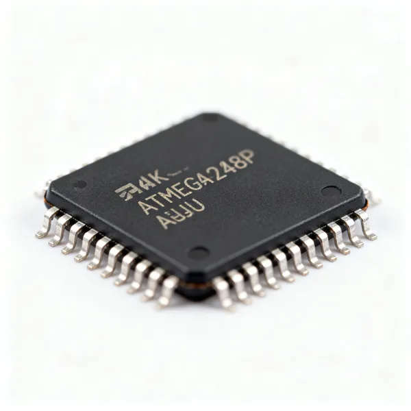
The ATMEGA328P-AU is an 8-bit microcontroller from the AVR family, manufactured by Microchip Technology. It is widely recognized for its efficient power consumption and robust performance, which make it suitable for a variety of applications, including embedded systems, IoT devices, and automation projects. The microcontroller operates at a maximum frequency of 20 MHz and includes 32 KB of flash memory, 2 KB of SRAM, and 1 KB of EEPROM. Its architecture supports a wide range of peripherals, including analog-to-digital converters (ADCs), timers, and serial communication interfaces.
Key features of the ATMEGA328P-AU include its RISC architecture, which allows for efficient instruction execution, and its capability to operate in both low-power and high-performance modes. Additionally, the microcontroller supports various programming interfaces, such as SPI, I2C, and UART, providing flexibility in connectivity and communication. Understanding these core concepts is crucial for engineers to effectively integrate the ATMEGA328P-AU into their designs and troubleshoot any issues that may arise.
Detailed Specifications
| Parameter | Value | Units | Notes |
|---|---|---|---|
| Maximum Operating Frequency | 20 | MHz | Optimal for high-speed applications |
| Flash Memory | 32 | KB | Non-volatile memory for program storage |
| SRAM | 2 | KB | Volatile memory for runtime data |
| EEPROM | 1 | KB | Non-volatile memory for data retention |
| ADC Resolution | 10 | bits | Supports up to 16 channels |
| Operating Voltage | 1.8 - 5.5 | V | Wide range for diverse applications |
| Power Consumption (Active Mode) | 0.2 | mA/MHz | Low power consumption for efficiency |
| Temperature Range | -40 to 85 | °C | Suitable for industrial environments |
| Package Type | TQFP | - | Thin Quad Flat Package for compact designs |
| Number of I/O Pins | 23 | - | Flexible I/O for various peripherals |
The table above provides a detailed look at the key parameters of the ATMEGA328P-AU microcontroller. Understanding these specifications is crucial when designing and implementing systems that rely on this component. For instance, the maximum operating frequency of 20 MHz allows for high-speed processing, making it ideal for time-critical applications. The availability of 32 KB of flash memory ensures ample space for program storage, while the 2 KB of SRAM and 1 KB of EEPROM provide sufficient memory for runtime and data retention needs. Additionally, the wide operating voltage range and extended temperature range make the ATMEGA328P-AU suitable for a variety of environments, from consumer electronics to industrial automation.
Design Considerations
When designing systems with the ATMEGA328P-AU, engineers must consider several critical factors to ensure optimal performance and reliability. First and foremost, power management is essential. The microcontroller's low power consumption is advantageous, but designers should implement strategies such as sleep modes and power gating to further minimize energy usage. Additionally, selecting the appropriate clock source and configuring the clock settings correctly is vital for achieving the desired performance levels.
Another important consideration is the layout of the printed circuit board (PCB). Proper PCB design can significantly impact signal integrity and thermal management. Engineers should pay close attention to the placement of decoupling capacitors and ensure that traces are designed to minimize electromagnetic interference. Moreover, the use of proper grounding techniques can help reduce noise and improve the overall stability of the system.
Interfacing with peripherals is another crucial aspect of design. The ATMEGA328P-AU supports various communication protocols, including SPI, I2C, and UART. Selecting the right protocol based on the application requirements and ensuring correct configuration is essential for seamless communication with external devices. Engineers should also consider the use of pull-up or pull-down resistors to ensure reliable signal levels on I/O pins.
| Design Guideline | Description | Notes |
|---|---|---|
| Power Management | Implement sleep modes and power gating | Reduces energy consumption |
| Clock Configuration | Choose appropriate clock source and settings | Ensures optimal performance |
| PCB Layout | Optimize trace design and capacitor placement | Improves signal integrity |
| Signal Integrity | Minimize EMI through proper design | Reduces noise and interference |
| Grounding Techniques | Use proper grounding methods | Enhances system stability |
| Peripheral Interfacing | Select and configure communication protocols | Ensures reliable data exchange |
| I/O Pin Configuration | Use pull-up/pull-down resistors | Maintains signal levels |
| Thermal Management | Ensure adequate heat dissipation | Prevents overheating |
Step-by-Step Guide
To effectively troubleshoot and optimize systems using the ATMEGA328P-AU, follow these detailed steps:
- Initial Setup: Begin by ensuring that the microcontroller is properly powered and connected to the necessary components. Verify the power supply voltage is within the specified range of 1.8 to 5.5 V.
- Clock Configuration: Configure the clock source and settings according to the application's requirements. This involves selecting between internal and external oscillators and setting the appropriate prescaler values.
- Peripheral Initialization: Initialize the necessary peripherals, such as ADCs, timers, and communication interfaces. Ensure that each peripheral is configured correctly to match the intended functionality.
- Implement Power Management: Integrate power-saving techniques, such as sleep modes and power gating, to enhance energy efficiency. This is particularly important for battery-powered applications.
- Signal Integrity Checks: Review the PCB layout for any potential issues with trace design and decoupling capacitor placement. Make adjustments to reduce electromagnetic interference and improve signal quality.
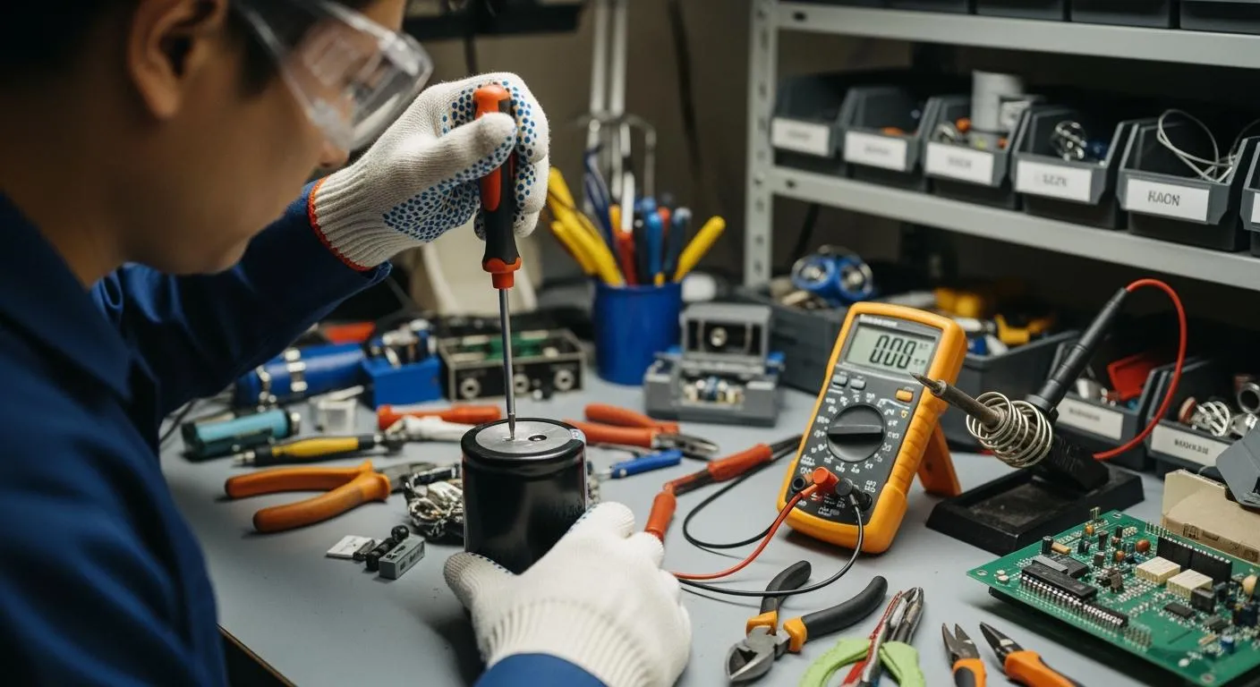
- Debugging and Testing: Use debugging tools, such as oscilloscopes and logic analyzers, to monitor signal levels and communication protocols. Identify and resolve any anomalies that may arise during operation.
- Thermal Management: Ensure that the microcontroller operates within its specified temperature range. Implement heat dissipation solutions, such as heat sinks or thermal pads, if necessary.
- Final Validation: Conduct a comprehensive validation of the system by testing it under various conditions. Verify that all functionalities work as intended and that performance meets the desired specifications.
Common Issues & Solutions
Engineers working with the ATMEGA328P-AU may encounter several common issues. Here are some problems and their solutions:
-
Problem: Microcontroller not booting up.
Solution: Check the power supply voltage and ensure it is within the specified range. Verify that the reset pin is properly connected. -
Problem: Communication failures with peripherals.
Solution: Ensure that the communication protocol is correctly configured. Check the wiring and signal levels on the I/O pins. -
Problem: Excessive power consumption.
Solution: Review the power management settings and implement sleep modes where possible. Check for any short circuits or component malfunctions. -
Problem: Inconsistent ADC readings.
Solution: Verify the reference voltage and ensure that the ADC is properly calibrated. Check for any noise interference in the signal path. -
Problem: Overheating issues.
Solution: Implement thermal management solutions, such as heat sinks, and ensure adequate airflow around the microcontroller.
Applications & Use Cases
The ATMEGA328P-AU is widely used in various applications due to its versatility and robust performance. In the consumer electronics sector, it is commonly found in devices such as remote controls, digital cameras, and home automation systems. In industrial settings, the microcontroller is used in process control, data acquisition systems, and motor control applications. Additionally, its low power consumption makes it ideal for battery-powered IoT devices, such as environmental sensors and wearable technology.
Selection & Sourcing Guide
When selecting and sourcing the ATMEGA328P-AU, engineers should consider factors such as availability, pricing, and supplier reputation. It is recommended to source components from authorized distributors to ensure authenticity and quality. For competitive pricing and fast delivery, visit IC Online, an authorized distributor of electronic components.
FAQ
-
What is the maximum operating frequency of the ATMEGA328P-AU?
The maximum operating frequency is 20 MHz. -
How much flash memory does the ATMEGA328P-AU have?
It has 32 KB of flash memory. -
What are the supported communication protocols?
The microcontroller supports SPI, I2C, and UART protocols. -
Can the ATMEGA328P-AU operate at low voltages?
Yes, it can operate at voltages as low as 1.8 V. -
What is the ADC resolution of the ATMEGA328P-AU?
The ADC resolution is 10 bits. -
How many I/O pins does the ATMEGA328P-AU have?
It has 23 I/O pins. -
What is the package type of the ATMEGA328P-AU?
The package type is TQFP (Thin Quad Flat Package). -
Is the ATMEGA328P-AU suitable for industrial applications?
Yes, it is suitable for industrial applications due to its wide temperature range and robust performance.
Conclusion
The ATMEGA328P-AU microcontroller is a powerful and versatile component that can be used in a wide range of applications. By understanding its technical parameters, design guidelines, and best practices, engineers can effectively troubleshoot and optimize their systems. Whether you are designing a consumer electronics device or an industrial automation system, the insights provided in this article will help you leverage the full potential of the ATMEGA328P-AU.