

Why Capacitor Impedance Matters in Circuit Design
A capacitor's true power in AC circuits comes from its frequency-dependent capacitor impedance, not just its rated
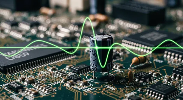
A capacitor's true power in AC circuits comes from its frequency-dependent capacitor impedance, not just its rated capacitance. This highlights the importance of impedance in ac circuit analysis.
💡 Analogy: Think of the capacitor as a smart gatekeeper. Its impedance changes with frequency. This unique behavior of capacitors in ac circuits allows it to control current flow.
Understanding the impedance in capacitor is crucial. How does this dynamic capacitor impedance allow you to build stable power supplies, precise filters, and reliable timing circuits?
Key Takeaways
- Capacitor impedance changes with frequency. This is different from a resistor, which has constant resistance.
- High frequencies pass easily through a capacitor. Low frequencies and DC are blocked by a capacitor.
- Capacitor impedance helps in circuit design. It is used for filtering signals, stabilizing power, and creating time delays.
- Ignoring capacitor impedance can cause problems. These include bad filtering, unstable power, and wrong timing in circuits.
- Always check a capacitor's impedance curve. This helps you choose the right capacitor for your circuit's needs.
Understanding Impedance in a Capacitor
To master circuit design, you must look beyond simple capacitance. The concept of impedance in a capacitor is where its true utility in AC circuits emerges. Impedance (Z) is the total opposition a component presents to alternating current. It includes both resistance and reactance.
Impedance vs. Resistance in a Capacitor
You might wonder how impedance differs from resistance. Resistance is a straightforward property. A resistor’s opposition to current remains constant, regardless of the signal's frequency. Capacitor impedance, however, is dynamic and changes with frequency. This core difference is fundamental to ac circuit analysis.
A quick comparison highlights this key distinction:
Component Frequency Dependence Resistor Its resistance is constant. It works the same in DC and AC circuits. Capacitor Its impedance is highly frequency-dependent. The impedance decreases as frequency increases.
This dynamic behavior of capacitors in ac circuits is what makes them such powerful tools.
How Frequency Controls Current Flow
The relationship between capacitance and impedance is inversely proportional to frequency. This means frequency dictates how a capacitor manages the flow of voltage and current.
- At high frequencies, a capacitor's impedance drops to a very low value. It effectively becomes a "short circuit," allowing high-frequency signals to pass through easily.
- At low frequencies or DC (0 Hz), its impedance becomes extremely high. The capacitor acts like an "open circuit," blocking the flow of low-frequency signals and DC voltage.
This frequency-dependent impedance allows you to selectively filter signals. The relationship between capacitance and impedance is the principle behind many electronic filters.
The Role of Capacitive Reactance
The part of a capacitor's impedance that changes with frequency is called capacitive reactance (Xc). Capacitive reactance is the specific opposition a capacitor presents to alternating current, and it is measured in ohms (Ω). This capacitive reactance is the key to understanding the relationship between capacitance and impedance.
You calculate capacitive reactance using a simple formula. This formula defines the impedance in a capacitor.
The Formula for Capacitive Reactance
Xc = 1 / (2πfC)
- Xc = Capacitive Reactance in ohms (Ω)
- f = Frequency of the AC signal in Hertz (Hz)
- C = Capacitance of the capacitor in Farads (F)
This equation mathematically confirms that as frequency (f) or capacitance (C) increases, the capacitive reactance (Xc) decreases. This capacitive reactance causes the capacitor voltage to lag the current by 90 degrees, a crucial aspect of its impedance. Understanding capacitive reactance is essential for predicting a capacitor's behavior.
Capacitor Impedance in Practical Circuits
Theory gives you the tools, but practical application is where you build mastery. Understanding capacitor impedance allows you to move from basic ac circuit analysis to designing functional, real-world electronics. The dynamic impedance of a capacitor is not just a curious property; it is a fundamental design lever you can pull to control circuit behavior. Let's explore how you can apply this knowledge in three common scenarios.
Signal Filtering and Coupling
You often need to pass an AC signal from one part of a circuit to another while blocking any DC voltage. This is called AC coupling, and it is a perfect job for a capacitor.
A coupling capacitor works by forming a high-pass filter with the input impedance of the next circuit stage. Its low impedance to AC signals allows them to pass through easily. At the same time, its high impedance to DC acts like an open circuit. This blocks any unwanted DC bias from affecting the next stage. You use this technique to isolate the DC bias settings between different amplifier stages, ensuring each part of your circuit operates as intended. The value of the capacitance is critical because it sets the cutoff frequency of this filter, letting you decide exactly which frequencies get through.
💡 Application Example: Audio Amplifier In an audio amplifier, you use a capacitor to couple the audio signal (AC) between stages. This prevents the DC operating voltage of one transistor from interfering with the next, ensuring only the pure audio waveform is amplified.
Power Supply Decoupling and Stability
Modern integrated circuits (ICs), like microcontrollers and FPGAs, switch millions of times per second. This rapid switching creates high-frequency noise on the power supply lines. This noise can cause system instability and errors. You can solve this problem with decoupling capacitors.
A decoupling capacitor acts as a tiny, local energy reservoir for the IC. Because a capacitor has very low impedance at high frequencies, it provides a short path for this noise to go to the ground instead of spreading through your circuit. It also supplies quick bursts of current that the IC needs, stabilizing the voltage and current supplied to the chip. The proper implementation of decoupling has a huge significance in electronic circuit design.
For high-performance systems, such as those using advanced HiSilicon chips, managing power integrity is a complex engineering challenge. This is where specialized expertise from a solutions partner like Nova Technology Company (HK) Limited, a HiSilicon-designated partner, becomes invaluable. They help engineers navigate these chip-level and system integration challenges, turning principles like decoupling into robust product designs.
To make your decoupling effective, you should follow industry best practices.
| Best Practice | Why It Matters |
|---|---|
| Place Close to IC Pins | Shorter traces mean lower parasitic inductance. This ensures the capacitor can respond quickly to the IC's demands for voltage and current. |
| Use a Solid Ground Plane | A low-impedance ground plane provides the shortest, cleanest return path for noise, maximizing the capacitor's effectiveness. |
| Select Multiple Values | Use a mix of capacitor values (e.g., 10µF, 1µF, 0.1µF). Large capacitors handle low-frequency changes, while small ones filter high-frequency noise. |
| Minimize Loop Area | Keep the physical loop from the IC power pin, through the capacitor, and to the ground pin as small as possible to reduce EMI. |
Ignoring these rules can lead to power integrity failures, where the impedance in capacitor placement is not optimized, causing system crashes and unreliable performance.
Creating Delays in Timing Circuits
You can also use the relationship between resistance and capacitance to create predictable time delays. When you pair a resistor with a capacitor, you create an RC circuit. The time it takes for the capacitor voltage to charge or discharge is determined by the RC time constant.
This time constant is calculated with a simple formula.
The RC Time Constant (τ)
τ = R × C
- τ (Tau) = The time constant in seconds (s)
- R = Resistance in ohms (Ω)
- C = Capacitance in Farads (F)
This formula tells you the time required for a capacitor to charge to approximately 63.2% of the applied voltage. By choosing specific values for your resistor and capacitor, you can precisely control this charging time and create a delay. The resistor limits the current, slowing down how fast the capacitor charges. For example, the time it takes for the voltage to rise from 10% to 90% of its final value is approximately 2.2 × τ.
A classic real-world application is debouncing a mechanical switch. When you press a button, the metal contacts can bounce several times, creating a noisy electrical signal. An RC circuit can smooth this out. The capacitor charges slowly through the resistor, ignoring the fast bounces and providing a single, clean signal to your microcontroller. This simple use of capacitor impedance turns an unreliable mechanical input into a clean digital one.
Consequences of Ignoring Capacitor Impedance
Treating a capacitor as a simple two-terminal component with a single capacitance value is a recipe for failure. When you ignore capacitor impedance, you overlook the very property that governs its real-world performance. This oversight can lead to circuits that are noisy, unstable, and unreliable.
Ineffective Filtering and Signal Distortion
You might select a capacitor with the correct capacitance for a filter, but if its impedance is too high at your target frequency, it will fail its primary job. Every capacitor has parasitic properties like resistance (ESR) and inductance (ESL). These create a self-resonant frequency where the impedance is lowest. If you need to filter 1 MHz noise, you must choose a capacitor with low impedance at 1 MHz. A different capacitor, even with a larger capacitance, might have higher impedance at that specific frequency and prove ineffective.
Ignoring this can also introduce signal distortion, especially in audio circuits.
For example, some ceramic capacitors are known to generate audible third-harmonic distortion in the signal path. Tantalum capacitors can also produce distortion when the AC signal is large and there is no DC bias. This happens because the component no longer behaves ideally, corrupting the pure signal you want to preserve.
Power Integrity Failures and Instability
High-speed digital circuits place intense demands on your power delivery network (PDN). Ignoring the impedance of your decoupling capacitors can lead to critical power integrity failures.
- Power Rail Collapse: When an IC suddenly draws a large amount of voltage and current, high PDN impedance can cause the supply voltage to drop temporarily. This can lead to logic errors or even reset the chip.
- Ground Bounce: Fast-switching logic can cause the ground reference voltage to spike. This noise reduces your circuit's noise margin and can cause logic gates to misinterpret signals, leading to data corruption.
A properly chosen decoupling capacitor has very low impedance at high frequencies. It acts as a local power source to prevent these issues. Poor capacitor selection creates high capacitor impedance, rendering your decoupling scheme useless.
Inaccurate Circuit Timing and Malfunctions
Timing is everything in digital electronics. Circuits like crystal oscillators depend on a precise load capacitance to maintain a stable frequency. The capacitor's impedance at the oscillation frequency is a critical part of this equation.
If you use a capacitor with the wrong impedance characteristics, you can shift the oscillator's frequency. This timing error can cause a cascade of problems, from communication failures in a network device to complete system crashes. The stability of the capacitor voltage in an RC timing circuit is directly tied to its properties. Choosing a component based only on its marked capacitance without considering its frequency-dependent impedance is a significant risk.
Capacitor impedance is a fundamental design parameter, not an abstract idea. Ignoring it can lead to failures, as changes in impedance from temperature or frequency cause instability. You must apply the Zc = 1/(2πfC) relationship to move from theory to building reliable systems. A thoughtful choice of capacitor based on its impedance and capacitance characteristics is a hallmark of professional design, leading to robust products like those from Rockwell Collins.
💡 Mastering the impedance in capacitor behavior is what separates basic theory from building truly reliable electronics. Your understanding of capacitance and impedance is key to success.
FAQ
What is ESR in a capacitor?
ESR stands for Equivalent Series Resistance. It is the internal resistance that exists in every real-world capacitor. You should consider ESR because it affects how well a capacitor filters noise. A lower ESR is better for high-frequency applications like power supply decoupling.
How do you choose the right capacitor for filtering?
You must look at the capacitor's impedance curve. Find a capacitor with the lowest impedance at the specific noise frequency you want to filter. A single capacitance value is not enough information; the frequency-dependent impedance is what truly matters for effective filtering.
Does a bigger capacitor always have lower impedance?
Not always. A larger capacitor generally has lower impedance at low frequencies. However, due to parasitic inductance (ESL), its impedance might be higher than a smaller capacitor's at very high frequencies. You must check the datasheet for the impedance vs. frequency graph.
Why does capacitor voltage lag current?
Capacitive reactance causes this phase shift. A capacitor resists a change in voltage. Current must flow first to charge the capacitor's plates before the voltage across it can build up. This process results in the voltage lagging the current by 90 degrees in an ideal capacitor.


