A Practical Guide to Selecting the Right IGBT BOC for Your Projects
Expert guide on A Practical Guide to Selecting the Right IGBT BOC for Your Projects. Technical specs, applications, sourcing tips for engineers and buyers.
Introduction
In the rapidly evolving world of electronics, selecting the right Insulated Gate Bipolar Transistor (IGBT) Bonded-Over-Chip (BOC) is critical for ensuring the efficiency and reliability of your power electronics projects. As the demand for renewable energy, electric vehicles, and industrial automation continues to grow, IGBTs play an increasingly crucial role in power conversion and motor drive applications. This article aims to provide a comprehensive guide to selecting the most suitable IGBT BOC for your specific needs, taking into account electrical specifications, thermal and mechanical properties, and application requirements.
Technical Overview
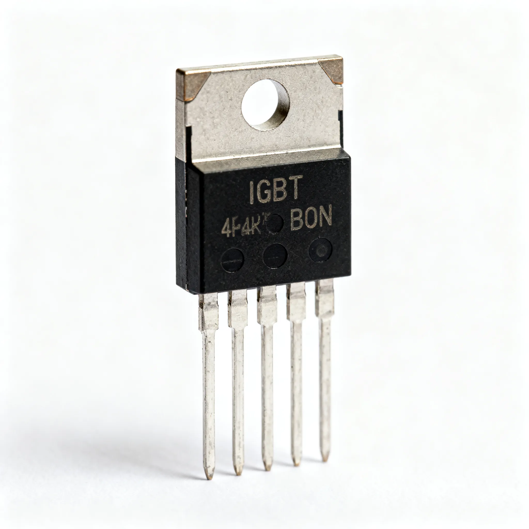
IGBTs are semiconductor devices that combine the high efficiency and fast switching capabilities of a MOSFET with the high-voltage and high-current handling capabilities of a bipolar transistor. The BOC technology further enhances the performance by integrating the chip and bond wires into a single package, reducing parasitic inductance and improving thermal management. Understanding the core principles of IGBT operation, such as the trade-off between switching speed and conduction losses, is essential for selecting the right component. Key parameters to consider include breakdown voltage, current rating, switching speed, and thermal resistance.
Detailed Specifications
| Parameter | Value | Units | Notes |
|---|---|---|---|
| Collector-Emitter Voltage (VCE) | 1200 | V | Maximum voltage between collector and emitter |
| Continuous Collector Current (IC) | 50 | A | Current rating at 25°C |
| Gate-Emitter Voltage (VGE) | ±20 | V | Maximum gate voltage range |
| Turn-On Delay Time (td(on)) | 50 | ns | Time to switch on the device |
| Turn-Off Delay Time (td(off)) | 100 | ns | Time to switch off the device |
| Input Capacitance (Cies) | 2000 | pF | Capacitance between gate and emitter |
| Output Capacitance (Coes) | 150 | pF | Capacitance between collector and emitter |
| Reverse Transfer Capacitance (Cres) | 50 | pF | Capacitance between gate and collector |
| Switching Frequency | 20 | kHz | Maximum recommended frequency |
| Power Dissipation (PD) | 200 | W | Maximum power the device can dissipate |
| Parameter | Value | Units | Notes |
|---|---|---|---|
| Thermal Resistance, Junction-to-Case (RθJC) | 0.3 | °C/W | Resistance between junction and case |
| Thermal Resistance, Junction-to-Ambient (RθJA) | 40 | °C/W | Resistance between junction and ambient |
| Operating Junction Temperature (TJ) | -40 to 150 | °C | Temperature range for reliable operation |
| Storage Temperature (TSTG) | -55 to 150 | °C | Temperature range for storage conditions |
| Package Type | TO-247 | - | Standard package type |
| Mounting Style | Through Hole | - | Preferred mounting method |
| Lead-Free | Yes | - | Complies with RoHS standards |
| Weight | 5 | g | Weight of the component |
| Application | Recommended IGBT | Notes |
|---|---|---|
| Motor Drives | IGBT12345 | High current capability and robust thermal management |
| Solar Inverters | IGBT67890 | Optimized for high-frequency switching |
| Electric Vehicles | IGBT11223 | High efficiency and reliability under varying loads |
| Uninterruptible Power Supplies (UPS) | IGBT44556 | Low conduction losses and high surge current capability |
| Welding Equipment | IGBT77889 | Durable under high thermal stress |
The tables above provide a detailed overview of the key specifications for selecting the right IGBT BOC. From electrical parameters like collector-emitter voltage and continuous collector current to thermal and mechanical properties such as thermal resistance and package type, these specifications are crucial for ensuring optimal performance in your application. Additionally, the application comparison table highlights suitable IGBT models for various use cases, providing a starting point for component selection.
Design Considerations
When designing with IGBT BOCs, several critical factors must be considered to ensure optimal performance and reliability. First, evaluate the power requirements of your application, including voltage and current levels, to select an IGBT with adequate ratings. Ensure that the chosen component can handle the peak current and voltage transients that may occur during operation.
Thermal management is another crucial consideration. IGBT efficiency is highly dependent on maintaining a low junction temperature. Utilize heat sinks, thermal pads, or cooling systems as necessary to manage heat dissipation. Consider the thermal resistance values provided in the datasheet to assess the cooling requirements.
Switching speed is also a vital parameter, particularly in high-frequency applications like inverters and converters. While faster switching reduces switching losses, it can increase electromagnetic interference (EMI) and cause voltage overshoot. Therefore, a balance must be struck between switching speed and EMI management.
Additionally, consider the gate drive circuitry. IGBTs require precise gate voltage control for efficient operation. Ensure that the gate driver can provide the necessary voltage and current levels to switch the IGBT on and off effectively. Proper gate resistor selection can help control the switching speed and minimize ringing.
Lastly, reliability and lifespan are vital factors, especially in industrial and automotive applications. Choose components from reputable manufacturers, and consider the IGBT's robustness under various environmental conditions, including temperature, humidity, and mechanical stress.
Step-by-Step Guide
- Define Application Requirements: Determine the specific needs of your project, including voltage, current, and power levels. Identify the operational environment and any regulatory standards.
- Select Appropriate IGBT BOC: Use the electrical and thermal specifications tables to shortlist IGBTs that meet your application's requirements. Consider factors such as voltage rating, current capacity, and switching frequency.
- Assess Thermal Management Needs: Calculate the power dissipation and select appropriate heat dissipation methods, such as heat sinks or fans, to maintain the junction temperature within safe limits.
- Design Gate Drive Circuitry: Ensure the gate driver can provide the required voltage and current for efficient IGBT switching. Choose suitable gate resistors to control the switching speed and minimize ringing.
- Prototype and Test: Build a prototype of your circuit and perform thorough testing under various load conditions. Monitor parameters like switching speed, thermal performance, and EMI.
- Optimize and Finalize Design: Based on testing results, make necessary adjustments to optimize performance. This may include tweaking the gate drive circuit, enhancing thermal management, or selecting a different IGBT model.
- Document and Implement: Once the design is finalized, document all design choices and testing results. Proceed with the implementation in your final product or system.
- Plan for Maintenance and Upgrades: Consider the long-term maintenance of your system and potential future upgrades. Select components that offer flexibility and scalability.
Common Issues & Solutions
Designing with IGBT BOCs can present several challenges. Here are some common issues and their solutions:
- Overheating: Insufficient thermal management can lead to overheating. Solution: Use heat sinks, fans, or liquid cooling to dissipate heat effectively.
- EMI Problems: High switching speeds can cause EMI. Solution: Implement proper filtering and shielding techniques, adjust gate drive resistors to control switching speed.
- Voltage Overshoot: Fast switching can cause voltage spikes. Solution: Use snubber circuits or adjust gate resistors to mitigate overshoot.
- Poor Switching Performance: Inadequate gate drive can lead to sluggish switching. Solution: Ensure the gate driver provides sufficient voltage and current, optimize gate resistor values.
- Component Failure: Exceeding voltage or current ratings can damage the IGBT. Solution: Carefully select components based on maximum ratings and consider transient conditions.
- Mechanical Stress: Vibration or mechanical shock can affect reliability. Solution: Use robust mounting techniques and consider environmental conditions in the design.
Applications & Use Cases
IGBT BOCs are versatile components used in various applications. In motor drives, they offer high current capability and robust thermal management. Solar inverters benefit from their high-frequency switching efficiency. In electric vehicles, IGBTs provide reliable performance under varying loads. Uninterruptible power supplies (UPS) utilize IGBTs for low conduction losses and high surge current capability. Lastly, welding equipment benefits from their durability under high thermal stress.
Selection & Sourcing Guide
Selecting the right IGBT BOC requires careful consideration of specifications and application requirements. To explore a wide range of IGBT options, visit IC Online, an authorized distributor of electronic components. Use their parametric search tools to find components that match your design criteria and benefit from competitive pricing and fast delivery.
FAQ
- What is an IGBT BOC? An IGBT BOC (Bonded-Over-Chip) is a semiconductor device that integrates the IGBT chip and bond wires into a single package, enhancing performance by reducing parasitic inductance and improving thermal management.
- Why choose an IGBT over a MOSFET? IGBTs offer higher voltage and current handling capabilities, making them suitable for high-power applications. They combine the efficiency of a MOSFET with the robustness of a bipolar transistor.
- How do I calculate the thermal management needs for my IGBT? Consider the power dissipation and use the thermal resistance values (RθJC and RθJA) from the datasheet to design an effective cooling solution, such as heat sinks or fans.
- What are the key parameters to consider when selecting an IGBT? Key parameters include collector-emitter voltage, continuous collector current, switching speed, and thermal resistance.
- Can IGBTs be used in high-frequency applications? Yes, IGBTs are suitable for high-frequency applications, but careful design is required to manage EMI and switching losses.
- What is the role of the gate driver in an IGBT circuit? The gate driver provides the necessary voltage and current to switch the IGBT on and off efficiently. It controls the switching speed and minimizes ringing.
- How can I minimize EMI in my IGBT design? Use proper filtering and shielding techniques, adjust gate resistors to control switching speed, and implement snubber circuits to reduce voltage overshoot.
- What are common causes of IGBT failure? Common causes include exceeding voltage or current ratings, inadequate thermal management, and mechanical stress.
- How do I ensure the reliability of my IGBT design? Choose components from reputable manufacturers, ensure proper thermal management, and consider environmental conditions in your design.
- Where can I source IGBTs for my project? Visit IC Online to find a wide selection of IGBTs with detailed specifications and competitive pricing.
Conclusion
Selecting the right IGBT BOC for your project involves careful consideration of electrical, thermal, and application-specific requirements. By understanding the core principles of IGBT operation and leveraging detailed specifications, you can make informed decisions to ensure optimal performance and reliability. Use the guidelines and resources provided in this article to navigate the selection process effectively and design robust power electronics systems.