Capacitor Diagram Insights for Industrial Electronics
Capacitor diagram interpretation is vital for selecting, installing, and troubleshooting capacitors in industrial electronics, ensuring system reliability and safety.
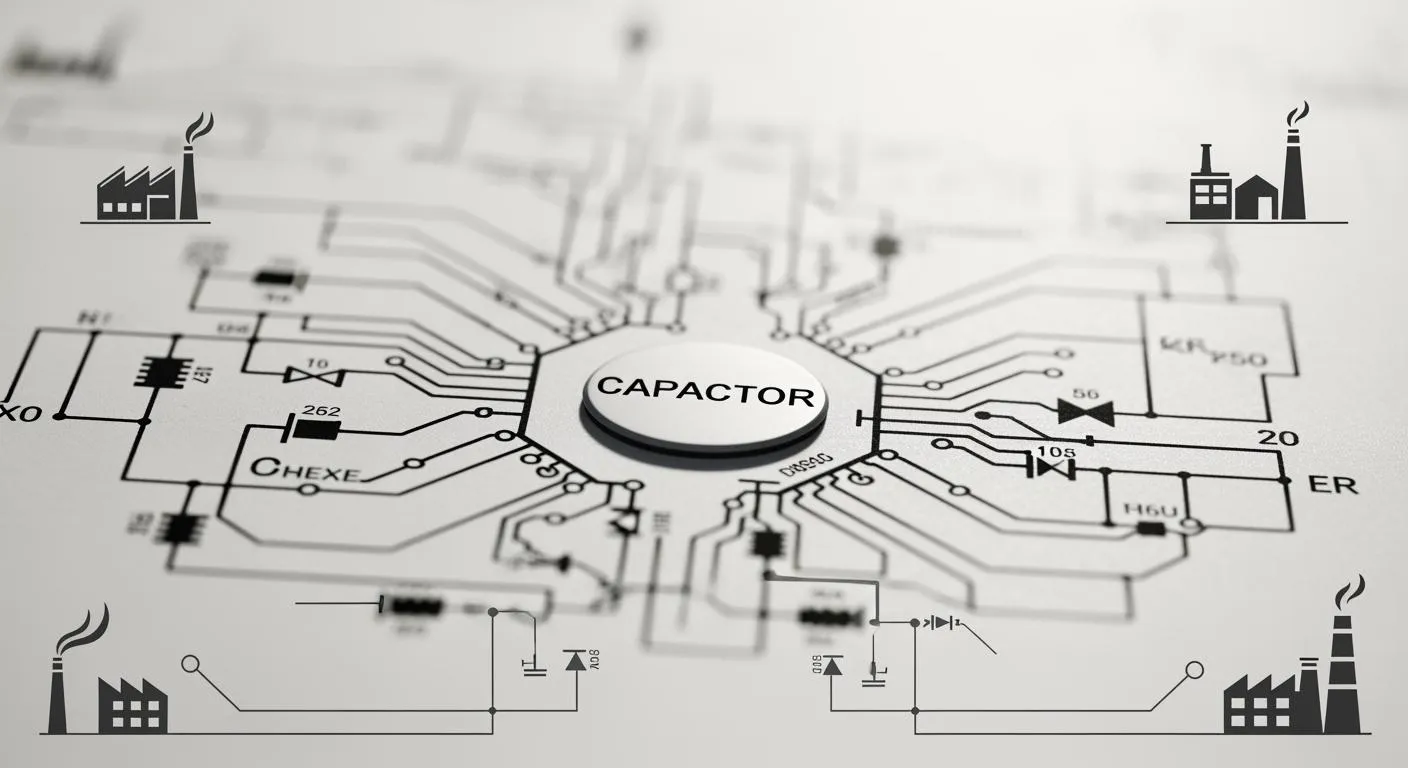
You encounter capacitors in almost every area of electronics, from small consumer devices to advanced industrial systems. When you read a capacitor diagram, you unlock the ability to understand how each capacitor shapes the circuit’s performance. These diagrams show you key details, such as the type of capacitor, its value, and its placement. Mastering capacitor diagram interpretation lets you spot potential issues quickly and select the right capacitor for each function. In industrial electronics, even a small change in capacitor tolerance can affect timing, filtering, or voltage stability. By reading a capacitor diagram with confidence, you improve system efficiency and reduce the risk of failures.
Key Takeaways
- Understanding capacitor diagrams helps you identify types, values, and placements, improving circuit performance.
- Capacitors are crucial for energy storage, filtering, and voltage stabilization in industrial electronics.
- Recognizing capacitor symbols in diagrams prevents errors and ensures correct component selection.
- Selecting the right capacitor involves considering capacitance, voltage rating, and application requirements.
- Following best practices in capacitor selection enhances reliability and efficiency in electronic systems.
Importance of Capacitors in Industrial Electronics
Key Functions of Capacitors
You see capacitors as essential electronic components in almost every industrial system. They play a major role in energy storage, filtering, voltage stabilization, and timing. When you work with industrial automation, you rely on capacitors for motor starters, inverters, and frequency converters. In automotive electronics, supercapacitors support regenerative braking and boost power supply efficiency. Industry 4.0 has increased the use of high-voltage capacitors in industrial controls and sensors. You also find capacitors in power systems, communication networks, computing, aerospace, and renewable energy applications.
- Capacitors store energy in an electrostatic field between two plates.
- They accumulate charge, with one plate holding positive charge and the other negative.
- The stored energy releases quickly to support transient loads and maintain voltage stability.
- Capacitors filter noise and regulate voltage, ensuring reliable operation of electronic devices.
You need basic knowledge of capacitors to understand their role in these applications. The basic use of capacitors includes smoothing voltage, supporting energy bursts, and protecting sensitive components. When you interpret a capacitor diagram, you must know the capacitance formula, unit conversions, and value identification methods. This foundation helps you optimize electronic systems and avoid errors.
Capacitor Structure and Operation
The structure of a capacitor affects its performance in industrial applications. You find three main types: electrolytic, ceramic, and film. Each type has unique characteristics and applications. The table below shows the differences:
| Capacitor Type | Dielectric Material | Structure Characteristics | Applications |
|---|---|---|---|
| Electrolytic | Aluminum oxide or tantalum pentoxide | Uses metal foil as anode, requires electrolyte, has polarity design issues | Power supply circuits |
| Ceramic | Barium titanate | Stacked ceramic layers, no polarity issues, good for high-frequency signals | Routers, high-frequency applications |
| Film | Organic films (PET, PP) | Plastic-like materials, low loss, long-term operation | Various electronic devices |
You must consider the materials, plate distance, and surface area when selecting a capacitor. These factors determine capacitance, energy storage, and voltage rating. Understanding the characteristics of capacitors helps you match the right component to each application. The physical structure also influences charge and discharge behavior, which is critical for timing and filtering.
Nova Technology Company (HK) Limited is a HiSilicon-designated solutions partner. The company specializes in integrated circuit solutions, system integration, and chip-level applications for industrial electronics. You can rely on their expertise for advanced electronic components and optimized system designs.
Common Capacitor Types and Their Symbols

Overview of Capacitor Types
You work with many capacitor types in industrial electronics. Each type has unique features that make it suitable for specific tasks. You often see ceramic, electrolytic, tantalum, film, polymer, and super capacitors in your projects. These types of capacitors help you solve different challenges, such as filtering, energy storage, and voltage regulation.
Here is a table that shows the most common capacitor types, their key features, and where you use them:
| Capacitor Type | Key Features and Applications |
|---|---|
| Ceramic | Highly stable, non-polar, used in high-frequency applications, ideal for coupling and filtering circuits. |
| Electrolytic | High capacitance, polarized, essential for energy storage and voltage smoothing in power supplies and audio systems. |
| Tantalum | Compact, reliable, stable capacitance, used in smartphones and medical devices, always polarized. |
| Film | Excellent electrical properties, low ESR, used in power supplies and motor drives, durable across temperature ranges. |
| Polymer | Improved electrolytics, low ESR, used in high-speed digital circuits and power management modules. |
| Super Capacitors | Extremely high capacitance, ideal for rapid energy storage and discharge in applications like regenerative braking. |
You choose ceramic capacitors for high-frequency circuits because they offer stability and reliability. You use electrolytic capacitors when you need high capacitance for power supply filtering. Tantalum capacitors give you compact size and stable performance in sensitive devices. Film capacitors work well in motor drives and power supplies. Polymer capacitors support high-speed digital circuits. Super capacitors handle rapid energy storage and release.
Schematic Symbols in Diagrams
You must recognize capacitor types in diagrams to build and repair circuits. Engineers use standard schematic symbols to show different types of capacitors. You see two parallel lines for non-polarized capacitors, such as ceramic and film types. For polarized capacitors, like electrolytic and tantalum, you see a straight line for the positive terminal and a curved line or a plus sign for the negative terminal.
Here is a table that compares how international standards represent capacitor symbols:
| Standard System | Polarized Capacitor Symbol | Voltage-dependent capacitor symbol |
|---|---|---|
| IEEE | Positive terminal marked with a '+' sign; negative terminal lacks curved lines (represented only by a short straight line) | A shape with a short parallel line on each side to indicate voltage dependency. |
| IEC | Positive terminal represented by a long straight line; negative terminal represented by a curved line (without a '+' sign) | A rectangle with a diagonal line through the center, with a small 'V' or arrow beside the diagonal line. |
- You spot non-polarized capacitors by two straight lines.
- You identify polarized capacitors by a straight and a curved line or a plus sign.
- You check for voltage-dependent capacitors by looking for extra marks, such as a diagonal line or arrow.
Tip: Always match the symbol to the correct capacitor type before you select or replace a component. This step prevents errors and keeps your circuit safe.
Reading a Capacitor Diagram

Step-by-Step Interpretation
You can analyze a capacitor diagram in industrial electronics by following a clear process. This approach helps you avoid mistakes and ensures you understand the role of each capacitor in the circuit. Here is a step-by-step guide:
-
Recognize Capacitor Symbols
Start by identifying the symbols in the diagram. Look for two parallel lines for non-polar capacitors. For polarized capacitors, check for a straight line paired with a curved line or a plus sign. These shapes tell you about the type and polarity. -
Read Capacitance Values
Examine the markings next to each capacitor symbol. You may see direct values like "10μF 16V" or codes such as "104K." Break down numeric codes into significant digits, multipliers, and tolerance. This step helps you select the right capacitor for the circuit. -
Understand Unit Conversions
Convert capacitance values between farads and smaller units. Remember that 1μF equals 1000nF or 1,000,000pF. Use the correct unit based on the circuit type and application. -
Labeling and Identification
Check for a "C" prefix, such as C1 or C20, which marks the component as a capacitor. Look for additional information like rated voltage or tolerance. Accurate labeling prevents confusion during assembly and troubleshooting. -
Circuit Positioning and Function
Observe where the capacitor sits in the circuit. Filter capacitors often connect between power and ground. Decoupling capacitors usually appear near IC power pins. Placement reveals the function, such as filtering, energy storage, or voltage regulation. -
Measuring Capacitance
Use a multimeter to measure capacitance when needed. Discharge the capacitor first. Select the correct range on the meter. Connect the red probe to the positive terminal and the black probe to the negative. Read the value and avoid measuring in-circuit or on charged capacitors.
Tip: Always check the routing logic. If a symbol connects to a positive terminal, it may indicate a polarized capacitor. This detail prevents installation errors.
Practical Tips and Common Mistakes
You can improve your accuracy and avoid common errors by following practical advice. Many engineers face challenges when reading capacitor diagrams, especially in industrial applications. Here are some tips and mistakes to watch for:
- Source capacitors from verified suppliers. Clear polarity markings reduce confusion.
- Perform incoming quality control checks. Verify capacitor markings before assembly.
- Follow PCB placement best practices. Include polarity indicators in the silkscreen layer.
- Always verify capacitor polarity before powering up the circuit. Incorrect polarity can cause damage.
- Use a multimeter to measure capacitance and confirm polarity, especially for unmarked capacitors.
- Consult datasheets for detailed specifications and marking conventions.
- Perform visual inspections to spot clues about capacitor orientation.
- Implement Automated Optical Inspection (AOI) and X-ray inspection after assembly for quality control.
- Simulate power delivery networks to avoid resonance issues that may lead to circuit failures.
- Follow PCB layout best practices to ensure proper capacitor placement and prevent overheating.
Common mistakes include:
- Unmarked or faded markings make identification difficult.
- Non-standard codes from some manufacturers cause confusion.
- Misinterpreting voltage ratings leads to capacitor failure.
Note: You can prevent most errors by double-checking markings, consulting datasheets, and using reliable measurement tools. Careful inspection and proper sourcing keep your circuit safe and efficient.
Selecting the Right Capacitor
Matching Capacitor to Application
You need to match each capacitor to its specific role in industrial electronics. Start by reading the diagram details and understanding the requirements of your applications. Use these criteria to guide your capacitor selection:
- Capacitance (C Value): Choose a value that meets the circuit’s needs.
- Voltage Rating: Pick a rating higher than the working voltage for safety.
- Equivalent Series Resistance (ESR): Lower ESR means less heating and better efficiency, especially in switching power supplies.
- Temperature Characteristics: Select capacitors that perform well in the temperature range of your applications.
- Lifespan and Reliability: For automotive and industrial applications, long-life and high-reliability capacitors are essential.
- Supply Chain and Certification: Work with certified manufacturers to ensure a stable supply.
Different types of capacitors fit different applications:
- Ceramic capacitors work well for filtering, decoupling, and high-frequency circuits because of their small size and low cost.
- Electrolytic capacitors provide large capacity for power supply filtering and energy storage, but they have limited lifespan.
- Film capacitors offer excellent stability and reliability, making them ideal for power electronics and precision circuits.
Environmental factors also affect your choice. For example, robust encapsulation protects mica capacitors from moisture in humid environments. Temperature-stable designs keep performance consistent during extreme changes.
In variable frequency drives, capacitors smooth DC voltage and stabilize energy. Filter capacitors suppress electrical noise, while snubber capacitors protect switching devices from voltage spikes.
Best Practices for Engineers
You can ensure reliable performance by following best practices for capacitor selection in industrial applications:
- Choose high-grade materials and tight tolerance for precision.
- Optimize voltage ratings with safety margins.
- Use robust encapsulation to prevent moisture ingress.
- Select proper lead configurations for mechanical stability.
- Apply advanced testing, such as thermal cycling, humidity exposure, and vibration tests.
| Design | Capacitor Arrangement | Frequency Range | Key Features |
|---|---|---|---|
| A | Parallel close to pin | >100MHz, 10–100MHz | Low ESL/ESR, noise suppression |
Capacitors play a crucial role in voltage balancing and energy storage. Careful selection and placement help maintain stable voltage and improve reliability in your applications.
Nova Technology Company (HK) Limited, a HiSilicon-designated solutions partner, specializes in chip-level solutions and system integration for the integrated circuit industry. You can rely on their expertise for advanced IC applications in industrial electronics.
You now understand how capacitor diagrams improve reliability and performance in industrial electronics. Decoupling capacitors stabilize power and reduce noise. To apply these insights, follow these steps:
- Start with a beginner’s guide to schematics.
- Use practical electronics resources for hands-on projects.
- Master core electrical concepts for safety.
| Continuous Learning Benefit | Result |
|---|---|
| Understanding strengths and limits | You design safer, more efficient systems. |
| Applying principles | You confidently use capacitors in advanced circuits. |
Stay curious and review guides on schematics and ESR. Careful attention to diagrams helps you build better, safer circuits.
FAQ
How do you identify a capacitor’s polarity in a diagram?
You look for a straight line and a curved line or a plus sign. The straight line marks the positive terminal. The curved line or minus sign shows the negative terminal. Always check the symbol before installation.
What happens if you install a capacitor with the wrong polarity?
You risk damaging the capacitor. The circuit may fail or the capacitor could leak or explode. Always verify polarity before connecting a polarized capacitor.
Why do you need different capacitor types in industrial electronics?
You select capacitor types based on their properties. Ceramic capacitors handle high frequencies. Electrolytic capacitors store more energy. Film capacitors offer stability. Each type fits a specific role in your circuit.
How can you measure a capacitor’s value?
You use a digital multimeter with a capacitance setting. Discharge the capacitor first. Connect the probes to the terminals. Read the value on the display. Avoid measuring in-circuit.
What does ESR mean and why is it important?
ESR stands for Equivalent Series Resistance. You want low ESR for efficient energy transfer and less heat. High ESR can cause performance issues, especially in power supply circuits.