Step-by-Step Guide to Capacitance Calculation in Electronics
You calculate capacitance in electronics by using the formula for capacitance, which relates the amount of electri
You calculate capacitance in electronics by using the formula for capacitance, which relates the amount of electric charge stored to the voltage across a capacitor. Capacitance plays a key role when you design or troubleshoot any circuit. If you understand how capacitance works, you can predict how components behave in series or parallel. The smallest capacitor in a series limits your total capacitance, which directly affects energy storage and voltage distribution. Accurate calculations help you avoid errors and improve circuit performance.
Key Takeaways
- Understand capacitance as the ability of a capacitor to store electric charge. Use the formula C = Q/V to calculate it.
- Capacitance affects circuit performance, especially in high-frequency applications. Choose capacitors with appropriate self-resonant frequencies.
- Identify the type of capacitor and gather necessary values before calculations. Different dielectrics and geometries influence capacitance.
- Use specific formulas for series and parallel configurations to find total capacitance. Remember that series reduces total capacitance while parallel increases it.
- Avoid common mistakes in calculations by considering total equivalent capacitance and stray capacitance. Always check the units used in your calculations.
Capacitance Fundamentals in Electronics
What Is Capacitance?
You encounter capacitance every time you work with electronic circuits. Capacitance is the characteristic that allows a circuit to store energy. This happens when two conductors with different electrical potentials are separated by an insulating material. The electric field between these conductors creates a capacity for energy storage. You measure capacitance in farads. The scientific definition states that capacitance is the ability of a capacitor to hold electric charge. The formula for capacitance is C = Q/U, where C stands for capacitance, Q is the charge in coulombs, and U is the voltage. Capacitance helps you understand how much charge a capacitor can store for a given voltage.
Why Capacitance Matters
Capacitance affects how your circuits perform. You need to know how capacitance influences signal integrity, especially in high-frequency applications. The self-resonant frequency of capacitors is important. When the operating frequency gets close to this value, filtering efficiency drops and signal quality suffers. You must select capacitors with self-resonant frequencies higher than your circuit’s operating frequency. Parasitic capacitance can also impact performance. It exists between parts of a component or circuit due to their proximity. This unwanted capacitance can limit the operating frequency and bandwidth. See the table below for more details:
| Aspect | Description |
|---|---|
| Definition | Parasitic capacitance is the unwanted capacitance between parts of a component or circuit. |
| Impact on Performance | It can limit frequency and bandwidth, especially in high-frequency circuits. |
| Example | Significant in closely spaced wires or PCB traces, affecting circuit behavior. |
You also need to consider ripple current. Ripple current affects the internal temperature of capacitors, which impacts reliability and operational life. Capacitors with low equivalent series resistance minimize power dissipation and improve circuit performance.
Capacitor Fundamentals
Capacitor fundamentals help you choose the right component for your circuit. You find many types of capacitors in electronics:
- Ceramic capacitors are common for filtering and decoupling.
- Electrolytic capacitors offer high capacitance and are used in power supply filtering.
- Film capacitors are stable and reliable for high-frequency applications.
- Mica capacitors provide exceptional stability for RF circuits.
- Tantalum capacitors are compact and used in space-constrained designs.
- Glass capacitors are rare and used in high-reliability environments.
- Vacuum capacitors handle high voltage in RF power transmission.
- Paper capacitors appear in legacy or high-voltage equipment.
The dielectric material inside a capacitor increases capacitance by polarizing and creating a layer of opposite charge. This reduces the electric field between the plates, allowing the capacitor to store more charge at a lower voltage. The dielectric constant measures how much the material boosts capacitance. The formula for a parallel plate capacitor with a dielectric is (C=\kappa \varepsilon _{0} \dfrac{A}{d}), where κ is the dielectric constant.
Nova Technology Company (HK) Limited stands out as a HiSilicon-designated solutions partner. You benefit from their expertise in chip-level solutions, system integration, and advanced application scenarios. Their support helps you achieve reliable performance in semiconductor and IC projects.
Formula for Capacitance Explained
Capacitance Formula (C = Q/V)
You use the capacitance formula to find out how much charge a capacitor can store for a given voltage. The formula for capacitance is C = Q/V. Here, C stands for capacitance, Q is the charge measured in coulombs, and V is the voltage measured in volts. You see this relationship in every electronic circuit. The formula for capacitance comes from Gauss’s law, which helps you understand how electric fields and potential differences relate to stored charge. When you apply the capacitance formula, you can predict how a capacitor will behave in your circuit. You rely on this formula for capacitance to solve problems and design reliable systems.
Variables and Units
You need to know the variables in the capacitance formula. Capacitance is the ability of a capacitor to store charge relative to the voltage across it. The standard unit for capacitance is the farad (F). If a capacitor holds 1 coulomb of charge at 1 volt, its capacitance is 1 farad. You measure charge in coulombs and voltage in volts. The formula for capacitance shows you how these units connect. You often see smaller units like microfarads (μF), nanofarads (nF), and picofarads (pF) in practical circuits. You use these units to match the right capacitor to your circuit needs.
| Variable | Symbol | Unit | Description |
|---|---|---|---|
| Capacitance | C | Farad (F) | Amount of charge stored per volt |
| Charge | Q | Coulomb | Total electric charge |
| Voltage | V | Volt | Potential difference across capacitor |
Series and Parallel Capacitance
You often connect capacitors in series or parallel to adjust total capacitance. In series, the total capacitance decreases. You use the formula for capacitance in series:
1/C_total = 1/C1 + 1/C2 + 1/C3 ...
In parallel, the total capacitance increases. You use the formula for capacitance in parallel:
C_total = C1 + C2 + C3 ...
You must watch for variations in capacitor values. If you use capacitors rated at ±20%, the weakest one can exceed its voltage rating. Leakage current can cause instability, especially as capacitors age. You also need to consider stray capacitance. Stray capacitance happens between conductors in your circuit. It can affect performance at high frequencies. Stray capacitance can make components act like short circuits, create unwanted feedback paths, and cause transmission loss. You find stray capacitance between PCB tracks, wires, and even underground cables. You use useful formulas to estimate and minimize stray capacitance for better circuit performance.
Capacitance Calculation Steps
You can calculate capacitance in electronic circuits by following a clear process. This section guides you through each step, helping you understand how to work with different capacitor types and apply the correct formulas. You will see practical examples that show how to solve real-world capacitor problems.
Identify Capacitor Type
You start by identifying the type of capacitor you want to analyze. The calculation method depends on the capacitor's construction and the dielectric material inside. Different dielectric materials, such as air, mica, and paper, affect capacitance. Higher permittivity values in dielectrics lead to larger capacitance. You also find that capacitor types have unique geometries, which means you need specific formulas for each. The dielectric constant plays a crucial role in determining capacitance.
- Dielectric materials like air, mica, and paper are common in capacitors.
- The properties of the dielectric material influence capacitance.
- Higher permittivity increases capacitance.
- Capacitor geometry affects the calculation method.
You must check the datasheet for each real-world capacitor to find its type and dielectric material. This information helps you select the right formula for your applications.
Gather Values Needed
You need to collect all the values required for capacitance calculation. These values depend on the capacitor type and the circuit configuration. For a parallel plate capacitor, you need the area of the plates, the distance between them, and the dielectric constant. For other capacitors, you need the charge, voltage, and capacitance values.
| Required Value | Description |
|---|---|
| Charge (Q) | The total charge in coulombs, calculated using Q = C × V. |
| Voltage (V) | The voltage across the capacitor, used in series and parallel calculations. |
| Capacitance (C) | The capacitance in farads, which can vary for each capacitor in a circuit. |
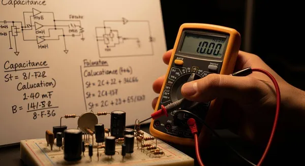
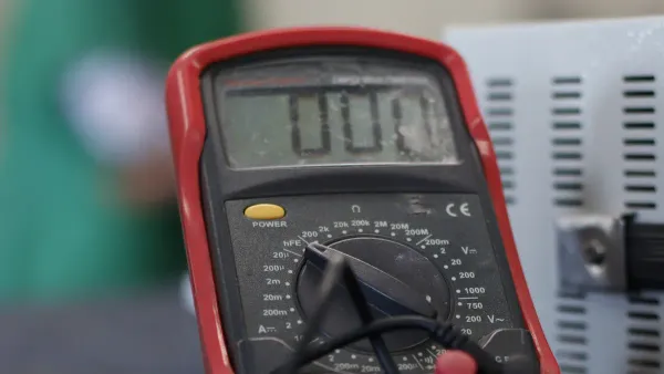
You can use tools like a digital multimeter or an LCR meter to measure capacitance in a circuit. These instruments help you verify the values for real-world capacitor applications.
Apply the Capacitance Formula
You apply the capacitance formula based on the values you gathered. The main formula is C = Q/V. You use this formula to find how much charge a capacitor stores for a given voltage. In circuits, you often need to calculate equivalent capacitance for series or parallel configurations.
- For capacitors in series, use the inverse sum rule:
( \dfrac{1}{C_S} = \dfrac{1}{C_1} + \dfrac{1}{C_2} + \dfrac{1}{C_3} + \dots ) - For capacitors in parallel, sum the capacitances:
( C_p = C_1 + C_2 + C_3 ) - The relationship Q = C × V helps you analyze circuit behavior.
- In series, capacitors share the same charge but have different voltages.
- In parallel, capacitors share the same voltage but have different charges.
You must check the tolerance of each real-world capacitor. Manufacturers specify tolerance as a percentage, such as ±10%. This value shows how much the actual capacitance can vary from the rated value. You find tolerance codes like 'K' for ±10% and short codes for capacitance values, such as μ47 for 0.47 μF.
Tip: Always check the datasheet for tolerance and preferred values before using a capacitor in your applications.
Parallel Plate Example
You can calculate the capacitance of a parallel plate capacitor using a step-by-step process. This example shows how to use the formula and find the charge stored.
- Identify the area of the plates (A) and the distance between them (d).
- Use the formula for capacitance:
( C = \varepsilon_0 \times \dfrac{A}{d} ) - Substitute the values into the equation to calculate capacitance.
- To find the charge stored, use Q = CV, substituting the calculated capacitance and the applied voltage.
Suppose you have a parallel plate capacitor with plate area 0.02 m², plate separation 0.001 m, and a dielectric constant of 1 (air). The permittivity of free space (( \varepsilon_0 )) is ( 8.85 \times 10^{-12} ) F/m.
- Calculate capacitance:
( C = 8.85 \times 10^{-12} \times \dfrac{0.02}{0.001} = 1.77 \times 10^{-10} ) F - If you apply 5 V, the charge stored is:
( Q = C \times V = 1.77 \times 10^{-10} \times 5 = 8.85 \times 10^{-10} ) C
You use this method for many applications, such as sensors and energy storage devices.
Series and Parallel Example
You often need to calculate equivalent capacitance for capacitors in series and parallel. The formulas help you design circuits for different applications.
| Configuration | Formula for Equivalent Capacitance |
|---|---|
| Series | ( \dfrac{1}{C_S} = \dfrac{1}{C_1} + \dfrac{1}{C_2} + \dfrac{1}{C_3} + \dots ) |
| Parallel | ( C_p = C_1 + C_2 + C_3 ) |
Suppose you have three capacitors:
- ( C_1 = 2 ) μF
- ( C_2 = 4 ) μF
- ( C_3 = 6 ) μF
Series Calculation:
( \dfrac{1}{C_S} = \dfrac{1}{2} + \dfrac{1}{4} + \dfrac{1}{6} )
( \dfrac{1}{C_S} = 0.5 + 0.25 + 0.1667 = 0.9167 )
( C_S = 1.09 ) μF
Parallel Calculation:
( C_p = 2 + 4 + 6 = 12 ) μF
You use these calculations to design circuits for filtering, timing, and energy storage applications. You must always check the voltage rating and tolerance for each real-world capacitor to ensure safe operation.
Note: For mixed series-parallel circuits, calculate the equivalent capacitance step by step. Find the total charge using Q = Ceq × V, then determine individual charges and voltages.
You now have a complete process for calculating capacitance in electronic circuits. You can apply these steps to any capacitor type and circuit configuration. This knowledge helps you avoid mistakes and improve performance in your applications.
Troubleshooting Capacitance Calculations
Common Mistakes
You can avoid many errors in capacitance calculations by understanding the most frequent mistakes. Many people assume that the load capacitance is just the value of each individual capacitor. In reality, you must use the total equivalent capacitance for the entire circuit. Some users ignore stray capacitance, which can change the expected results, especially in high-frequency designs. Others forget to tune the capacitors based on actual measurements, which leads to poor frequency accuracy.
- Assuming the load capacitance equals the value of one capacitor instead of the total equivalent capacitance.
- Ignoring stray capacitance, which can affect accuracy.
- Failing to adjust capacitors after measuring real values.
Incorrect calculations can cause problems in timing circuits, filter designs, and decoupling applications. For example, a 20% tolerance in a 10 μF capacitor can shift the frequency in a timer circuit by 20%. This shift disrupts the operation. In filter circuits, changes in capacitance can move the cutoff frequency and reduce signal quality. In power supply circuits, poor noise suppression can result from incorrect capacitance values.
Unit Conversion Tips
You often need to convert between units when working with capacitance. Most capacitors use microfarads (μF), nanofarads (nF), or picofarads (pF). Remember these conversions:
- 1 μF = 1,000 nF
- 1 nF = 1,000 pF
- 1 μF = 1,000,000 pF
Tip: Always check the units on your capacitor before plugging values into formulas. Mixing up units can lead to large errors in your calculations.
Practical Advice
You can improve the accuracy of your capacitance calculations by following a few practical steps:
- Address parasitic capacitance by using shielded cables and careful layout design.
- Use temperature-stable capacitors or apply correction factors for temperature changes.
- Choose precision components for critical circuits to reduce the impact of tolerance.
- Implement proper shielding and grounding to minimize errors from electromagnetic interference.
- Monitor environmental factors like temperature and humidity, as they can change capacitance and capacitive reactance.
| Environmental Factor | Effect on Capacitance |
|---|---|
| High Temperature | Can increase or decrease capacitance, lower insulation resistance, and affect capacitive reactance. |
| Low Temperature | May cause cracks and moisture issues, degrading performance and changing capacitive reactance. |
| High Humidity | Increases dielectric losses, reduces insulation resistance, and can lower capacitance. |
| Alternating Heat & Humidity | Accelerates moisture penetration, causing performance degradation and affecting capacitive reactance. |
You should always consider equivalent series resistance when selecting a capacitor. This value affects power loss and heat generation. Lower equivalent series resistance improves reliability and efficiency in your circuit.
You can calculate capacitance by identifying the capacitor type, gathering values, and applying the correct formula. Understanding how a capacitor stores charge and responds to voltage helps you select the right component for your circuit. Practice by wiring circuits, observing voltage changes, and adjusting values to match desired time constants. Remember, dielectric properties, temperature limits, and effective series resistance affect capacitor performance. To apply these skills, choose capacitors with proper voltage ratings and familiarize yourself with their typical values for safe and reliable circuit design.
FAQ
What is the main purpose of a capacitor in a circuit?
You use a capacitor to store and release electrical energy. Capacitors help you filter signals, smooth voltage, and manage timing in a circuit. They also protect sensitive components from voltage spikes.
How do you measure capacitance if you do not know the value?
You can use a digital multimeter or an LCR meter to measure capacitance. Connect the meter to the capacitor leads. The display shows the capacitance value directly.
Can you connect capacitors with different values in the same circuit?
Yes, you can connect capacitors with different values in series or parallel. The total capacitance changes based on the connection type. Always check the voltage rating for each capacitor before using them together.
Why does capacitance matter in high-frequency circuits?
Capacitance affects how signals move through a circuit at high frequencies. Too much or too little capacitance can cause signal loss, distortion, or unwanted noise. You must choose the right value for stable performance.
What happens if you use the wrong unit when calculating capacitance?
If you use the wrong unit, your calculation will be incorrect. This mistake can cause the circuit to fail or behave unpredictably. Always double-check units like microfarads, nanofarads, and picofarads.