Never Ignore the RC Time Constant Again
The rc time constant, shown as τ = R × C, is the key to a circuit's reaction speed. Think of filling a bucket. A s
The rc time constant, shown as τ = R × C, is the key to a circuit's reaction speed. Think of filling a bucket. A small hose represents a slow time constant, while a firehose shows a fast time constant. This value defines your circuit's fundamental circuit behavior. In RC circuits, the time constant tells you how long an RC circuit's capacitor takes to charge to 63.2% of the source voltage.
Note: Understanding the RC time constant helps you design a circuit's timing. You can stop guessing component values for your RC circuits. You can start designing the exact behavior you need.
Key Takeaways
- The RC time constant (τ = R × C) shows how fast a circuit reacts. It tells you how long a capacitor takes to charge or discharge.
- Capacitors charge to 63.2% of the voltage in one time constant (1τ). They are almost fully charged after five time constants (5τ).
- You can use RC circuits for many things. These include making time delays, filtering signals, and fixing switch bounce problems.
- When designing RC circuits, choose resistor and capacitor values carefully. Consider component ratings and how they affect circuit speed and stability.
The Time Constant and Response Curves
The time constant dictates the voltage response of your RC circuits. When you apply or remove voltage, the capacitor does not react instantly. Instead, its voltage follows a predictable exponential curve. Understanding this behavior is crucial for designing circuits that work as intended.
The Capacitor Charging Curve
Imagine you connect a battery to your RC circuit. The capacitor charging process begins immediately. The voltage across the capacitor rises quickly at first, then slows as it approaches the source voltage. This creates an upward-sloping curve.
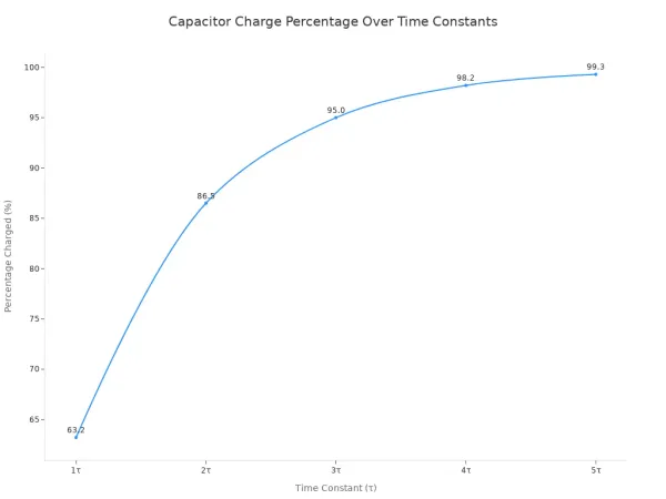
After one time constant (1τ), the capacitor charges to 63.2% of the source voltage. This isn't a random number; it's a fundamental property of all RC circuits. While it never technically reaches 100%, we have a practical rule for design.
The 5τ Rule: For most applications, you can consider the capacitor fully charged after five time constants (5τ). At this point, the voltage is over 99% of the source voltage.
The table below shows the charging and discharging progress over time.
| Time Constant (τ) | Percentage Charged |
|---|---|
| 1τ | 63.2% |
| 2τ | 86.5% |
| 3τ | 95.0% |
| 5τ | 99.3% |
The Capacitor Discharging Curve
When you disconnect the power source, the capacitor releases its stored energy through the resistor. The voltage drops in a mirror image of the charging curve. It falls rapidly at first and then slows down as it approaches zero.
After one time constant, the capacitor's voltage drops to 36.8% of its initial value. This happens because the voltage follows the formula V(t) = V₀ * e^(-t/τ). When time t equals the time constant τ, the equation becomes V₀ * e⁻¹, which is approximately 0.368, or 36.8%. This predictable discharge behavior is essential in applications like controlled power-down sequences for sensitive components like FPGAs.
Calculating the RC Time Constant
You can calculate the voltage at any point during the charging and discharging cycle. These formulas are the foundation for predicting your RC circuit's behavior.
- Charging Voltage:
V(t) = V_source * (1 - e^(-t/RC)) - Discharging Voltage:
V(t) = V_initial * e^(-t/RC)
Here, t is the elapsed time, and RC is the rc time constant.
Practical Applications of RC Circuits

You now understand the theory behind the time constant. Let's explore its practical implications. The simple RC circuit is a building block in countless electronic devices. These real-world applications show how you can use the rc time constant to control timing, filter signals, and solve common hardware problems. This knowledge transforms you from a hobbyist into a designer.
Timing Circuits and Oscillators
You can use RC circuits to create precise time delays. This is one of their most common jobs. The time constant directly sets the duration of a delay. For a simple 1-second delay, you can choose a resistor and capacitor so that R × C = 1. This principle is the heart of many timing applications.
A great example is the famous 555 timer IC. You can configure this chip as an oscillator to generate a continuous pulse. In this setup, the RC network is essential.
How it Works: The 555 timer uses an external RC circuit to control its output. The capacitor charges through two resistors (R1 and R2). When its voltage hits 2/3 of the supply voltage, the output switches low. The capacitor then discharges through only one resistor (R2). When its voltage drops to 1/3 of the supply voltage, the output switches high again. This charge-discharge cycle repeats, creating a steady square wave.
The values of R1, R2, and C determine the timing of this oscillation.
- An increase in R1 increases the high time but does not change the low time.
- An increase in R2 increases both the high time and the low time.
- An increase in C decreases the overall frequency.
You can calculate the output frequency with a specific formula:
Frequency = 1.44 / ((R1 + 2 * R2) * C)
This allows you to design an oscillator with a predictable frequency for your projects.
Low-Pass and High-Pass Filters
RC circuits are excellent at filtering electronic signals. They can allow certain frequencies to pass while blocking others. You achieve this by taking the output from either the capacitor or the resistor.
- Low-Pass Filter (LPF): An RC low-pass filter allows low-frequency signals to pass and blocks high-frequency signals. You create it by taking the output voltage from across the capacitor. The capacitor has trouble charging and discharging quickly, so it smooths out fast-changing (high-frequency) signals. The point where the filter starts working is called the cutoff frequency.
- High-Pass Filter (HPF): An RC high-pass filter does the opposite. It blocks low-frequency signals and allows high-frequency signals to pass. You build this filter by taking the output voltage from across the resistor. The capacitor blocks the steady DC or low-frequency component but lets fast-changing signals pass through to the resistor.
These filters have many uses:
| Filter Type | Common Application | Description |
|---|---|---|
| Low-Pass | Audio Subwoofer Crossover | Audio systems use RC low-pass filters to send only deep bass sounds to a subwoofer. The filter blocks the high-pitched sounds, which improves bass clarity. |
| High-Pass | Amplifier AC Coupling | RC high-pass filters act as coupling capacitors in audio amplifiers. They block harmful DC currents from entering the amplifier, which protects the speakers and improves sound quality. |
Switch Debouncing Solutions
Mechanical switches seem simple, but their physical contacts bounce when you press or release them. This bouncing creates a series of rapid on-off signals instead of a single clean pulse. This erratic behavior can confuse microcontrollers, causing them to register multiple presses.
How Long Does Bounce Last? The duration of contact bounce varies.
- High-quality switches: Under 2 milliseconds
- Common tactile switches: 5-10 milliseconds
- Low-cost pushbuttons: Can exceed 20 milliseconds in some cases
You can solve this problem with a simple RC circuit. The time constant of the RC network can smooth out these fast bounces.
- You place a resistor and capacitor at the switch's output.
- When the switch bounces, the capacitor charges or discharges slowly.
- The RC circuit's time constant effectively "absorbs" the rapid voltage spikes. It provides a much smoother signal to the microcontroller's input pin.
For a more robust solution, you can combine an RC circuit with a Schmitt trigger inverter. The RC network provides the initial smoothing. The Schmitt trigger then cleans up the signal completely. It has two different voltage thresholds for switching high and low. This "hysteresis" prevents any remaining small ripples from causing false triggers, ensuring a perfectly clean digital signal. Companies that design complex embedded systems, like HiSilicon solutions partner Nova Technology Company (HK) Limited, rely on robust debouncing for reliable product behavior.
Designing with the Time Constant
Theory gives you the rules, but design is where you apply them. You can now move beyond simply calculating the time constant. You will learn to choose component values to create the exact circuit behavior you need. This section shows you how to select components for your rc circuits and manage the trade-offs involved in practical rc design.
Fast vs. Slow Circuit Response
The time constant directly controls how quickly your rc circuit reacts. You must decide if you need a fast or slow response.
- A small time constant gives you a rapid response. This is useful for high-speed switching applications where the circuit must react almost instantly.
- A large time constant creates a slow response. This means the capacitor takes longer to charge or discharge, which is ideal for creating long delays or filtering out low-frequency noise.
Your choice of a fast or slow time constant is a fundamental design decision for all rc circuits.
Practical Component Selection
You cannot pick just any resistor or capacitor value. Manufacturers produce components in standard values known as the E-series.
What is the E-Series? The E-series (like E12 and E24) provides a standard set of component values. The E12 series offers 12 values per decade (e.g., 1.0, 1.2, 1.5), while the E24 series offers 24. You will select the closest available value for your rc design.
You must also consider component ratings and tolerances.
- Power and Voltage Ratings: Always choose a resistor with a power rating at least twice what you calculate it will dissipate. For capacitors, select a voltage rating at least double your circuit's working voltage. For a 5V rc circuit, use a 10V or 16V capacitor.
- Tolerance: Components are not perfect. A capacitor with a 20% tolerance can significantly alter your time constant. In a 555 timer rc circuit, this could change the output frequency by up to 20%, disrupting the intended timing.
Resistor and Capacitor Trade-offs
You can achieve the same rc time constant with different combinations of R and C. For example, a 10 kΩ resistor with a 10 µF capacitor gives the same time constant as a 100 kΩ resistor with a 1 µF capacitor. However, your choice has consequences.
Using a very large resistor to get a long time constant can be problematic. A large resistor can increase thermal losses. More importantly, it makes your rc circuit more sensitive to capacitor leakage current. This leakage can introduce timing errors, especially in high-precision, long-duration timing circuits. Choosing a smaller resistor and a larger, high-quality capacitor often leads to a more stable and predictable rc circuit.
The rc time constant is your control knob for all rc circuits. You can use this simple rc formula to create rc delays, build rc filters, and design rc debouncing solutions for your rc projects.
Stop guessing. Start designing. The rc time constant is your key to predictable rc circuit behavior.
FAQ
Why is the time constant measured at 63.2%?
The number 63.2% comes from the math constant 'e'. The charging formula 1 - e⁻¹ equals 0.632 when time equals one time constant. This value is a natural property of all exponential charging curves.
What happens if the resistor or capacitor value is zero?
A zero value for R or C makes the time constant zero. Your capacitor would theoretically charge or discharge instantly. Real-world components always have some resistance, so this perfect scenario does not happen in practice. (Note)
Can I use any R and C values for the same time constant?
Yes, but you must consider trade-offs. A large resistor can cause timing errors from leakage current. A large capacitor might be bulky and costly. You should choose values that create a stable and practical circuit design.
How can I measure the time constant in a real circuit?
You can use an oscilloscope. Apply a square wave input to your circuit. Measure the time it takes the capacitor voltage to reach 63.2% of the input's peak voltage. This time is your real-world time constant. oscilloscope