Curious About an Inverting Op Amp? Get Simple Answers Here
An inverting op amp is a fundamental circuit. It takes your input signal, makes it stronger, and flips its polarit
An inverting op amp is a fundamental circuit. It takes your input signal, makes it stronger, and flips its polarity. This means the output is 180 degrees out of phase with the input. The circuit uses an operational amplifier as its core component. You apply the signal to the op-amp's inverting (-) terminal.
This simple inverting amplifier configuration is a cornerstone of analog electronics. As a HiSilicon-designated solutions partner, we at Nova Technology Company (HK) Limited see the growing importance of this amplifier. The op-amp market is expanding, driven by its use in EVs and smart devices.
Key Takeaways
- An inverting op amp makes an electrical signal stronger and flips its direction. It uses a special chip called an op-amp.
- The circuit's design uses two resistors to control how much the signal gets stronger. One resistor is for the input, and the other is for feedback.
- A key idea is 'virtual ground.' This means one part of the op-amp acts like it's connected to ground, even when it's not. This helps the circuit work steadily.
- You can calculate how much the signal will change using a simple formula. This formula uses the values of the two resistors.
- Inverting op-amps are useful in many devices. These include audio mixers and signal filters. They are important parts of modern electronics.
How an Inverting Op Amp Works
You can understand the inverting op amp by looking at its three key parts. These are the circuit layout, the core component, and a key working principle. Let's break down each one.
The Basic Circuit Layout
The design of an inverting amplifier is simple and effective. You build the circuit around an operational amplifier.
- You connect your input signal (
V_in) to a resistor called the input resistor (R_in). - This resistor then connects to the op-amp's inverting (-) input pin.
- You connect another resistor, the feedback resistor (
R_f), from the op-amp's output pin back to the inverting (-) input pin. - Finally, you connect the non-inverting (+) input pin directly to ground (0V).
This feedback loop is the secret to the amplifier's stable and predictable behavior.
Core Component: The Operational Amplifier
The heart of the circuit is the operational amplifier, or op-amp. An op-amp is a high-gain electronic voltage amplifier. In theory, an ideal op-amp has perfect characteristics.
What Makes an Ideal Op-Amp? An ideal amplifier would have:
- Infinite open-loop gain (it can amplify a signal by an infinite amount).
- Infinite input impedance (it draws zero current from the input source).
- Zero output impedance (it can supply any amount of current to the load).
- Infinite bandwidth (it can amplify any frequency).
- Zero noise and zero input offset voltage.
Real-world op-amps are not perfect, but they come very close. For example, a common op-amp like the LM741 has a very high "Large Signal Voltage Gain."
| Parameter | Min | Typ | Max | Unit |
|---|---|---|---|---|
| Large signal voltage gain | 50 | 200 | - | V/mV |
A typical gain of 200 V/mV means a 1 millivolt difference between the inputs could produce a 200-volt output! This extremely high gain is what makes the op-amp so useful. To connect this in a real circuit, you need to know the pinout. The popular LM358 contains two op-amps in one chip.
| PIN Number | PIN Name | PIN Function |
|---|---|---|
| 1 | OUT1 | Output of amplifier 1 |
| 2 | IN1- | Inverting input of amplifier 1 |
| 3 | IN1+ | Non-inverting input of amplifier 1 |
| 4 | V- | Negative Supply / Ground |
| 5 | IN2+ | Non-inverting input of amplifier 2 |
| 6 | IN2- | Inverting input of amplifier 2 |
| 7 | OUT2 | Output of amplifier 2 |
| 8 | V+ | Positive Supply |
The 'Virtual Ground' Principle
The "virtual ground" is the most important concept for understanding an inverting op amp. The op-amp always tries to make the voltage at its two inputs equal. This is a direct result of the negative feedback you created with the resistor R_f.
- You connected the non-inverting (+) input to ground, so its voltage is 0V.
- Because of negative feedback, the op-amp adjusts its output to force the inverting (-) input to also be 0V.
This point becomes a virtual ground. It behaves like it is connected to ground, but it is not physically connected. This action stabilizes the op-amp and prevents its output from swinging wildly to the maximum or minimum voltage.
Note: The virtual ground principle is not always true. It only works when negative feedback is active. If the op-amp needs to produce an output voltage higher or lower than its power supply, it saturates. In saturation, the virtual ground disappears, and the op-amp no longer operates as a linear amplifier.
Gain and Purpose of an Inverting Amplifier
An inverting op amp has two primary jobs: it amplifies a signal and it inverts it. The beauty of this circuit is that you control exactly how much it amplifies the signal using just two resistors. This predictability is why engineers, including HiSilicon-designated solutions partners like Nova Technology Company (HK) Limited, rely on this fundamental amplifier in complex designs for modern electronics. You can easily set the circuit to perform a specific task.
Signal Amplification and Inversion
The name "inverting amplifier" tells you its two main functions.
- Amplification: The amplifier takes a small input signal and produces a larger output signal. Think of it like turning up the volume on a stereo. The amount of amplification is called the "gain."
- Inversion: The circuit flips the polarity of the signal. A positive input voltage becomes a negative output voltage. A negative input voltage becomes a positive output voltage. This is also called a 180-degree phase shift.
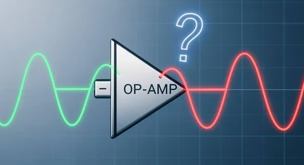
Visualizing Inversion on an Oscilloscope 🔬
If you connect an oscilloscope to your circuit, you can see this effect clearly. An oscilloscope demonstrates the 180-degree phase shift by displaying both the input and output signals at the same time. You will see the output signal appear as the inverse wave of the input signal. When the input wave goes up, the output wave goes down.
Calculating Voltage Gain
You can precisely set the gain of your inverting amplifier. The gain depends entirely on the values of the input resistor (R_in) and the feedback resistor (R_f). This makes the op-amp circuit incredibly stable and predictable.
The formula for the voltage gain (A_v) is simple:
Gain (Av) = - (R_f / R_in)
The negative sign (-) in the formula is important. It does not just mean the number is negative. It signifies that the op-amp inverts the signal.
Let's Calculate! An Example
Imagine you build a circuit with these components:
- Feedback Resistor (
R_f) = 20 kΩ- Input Resistor (
R_in) = 2 kΩFirst, you calculate the gain:
Gain = - (20 kΩ / 2 kΩ) = -10The gain of your amplifier is -10.
Now, if you apply a 0.5 Volt input signal (
V_in), you can find the output voltage (V_out):
V_out = V_in * Gain = 0.5V * (-10) = -5VYour 0.5V input signal produces a -5V output signal. The signal is now 10 times stronger and its polarity is flipped.
Inverting vs. Non-Inverting Op-Amps
The inverting op amp is not your only option. Its counterpart is the non-inverting amplifier. You choose between them based on your circuit's needs. Key factors include signal polarity, desired gain, and how the amplifier interacts with your signal source. Understanding their differences helps you select the right tool for your project.
Input and Output Differences
The most immediate differences between the two configurations are where you apply the input signal and what happens to the output. An inverting amplifier flips the signal's phase, while a non-inverting op-amp preserves it. This choice also impacts how much current your circuit draws from the source.
You can see the main distinctions in this simple comparison:
| Feature | Inverting Amplifier | Non-Inverting Amplifier |
|---|---|---|
| Input Terminal | Signal goes to the inverting (-) pin. | Signal goes to the non-inverting (+) pin. |
| Output Polarity | Flips the signal (180° phase shift). | Keeps the signal in phase (0° phase shift). |
| Input Impedance | Set by the input resistor (R_in). | Very high, minimizing load on the source. |
Gain Characteristics
The way you calculate gain is also different. This affects the range of amplification you can achieve. The gain of an inverting amplifier can be less than one, allowing you to reduce a signal's voltage.
In contrast, a non-inverting op-amp always has a gain of one or more. Its gain formula is Av = 1 + (R_f / R_in). Because resistor values cannot be negative, the ratio (R_f / R_in) is always zero or positive. Adding 1 to this value means the gain can never be less than one.
Special Case: The Unity Gain Buffer
You can configure a non-inverting amplifier as a unity gain buffer, also called a voltage follower. You do this by removing the resistors and connecting the output directly to the inverting (-) input.
- The gain is exactly 1 (
V_out=V_in).- It does not amplify voltage but provides high current gain.
- It is extremely useful for isolating circuits, as its high input impedance prevents it from loading down the signal source.
This buffer is a perfect example of how a simple op-amp circuit can solve complex engineering problems.
You now know the inverting op amp is a core circuit in electronics. This amplifier uses an operational amplifier and negative feedback. It creates an output signal that is stronger and inverted. You can easily set the gain of this inverting amplifier with just two resistors. This makes the op-amp circuit very predictable. The simple op-amp remains a vital building block. Its principles power the next generation of amplifier technology.
The classic op-amp continues to evolve for modern needs:
- Chopper-Stabilized Op-Amps are reducing noise for high-precision tasks.
- Rail-to-Rail designs maximize the signal range in low-voltage devices.
- Digitally Assisted Analog circuits use digital controls to improve analog accuracy.
FAQ
What happens if R_f and R_in are the same value?
If R_f and R_in are equal, the gain is exactly -1. Your output signal will have the same strength as the input signal. The circuit only inverts the signal's polarity. This useful configuration is called a unity gain inverter.
Can an inverting op-amp make a signal smaller?
Yes, you can make a signal smaller. You achieve this by making the input resistor (R_in) larger than the feedback resistor (R_f). This results in a gain between 0 and -1. The circuit then attenuates, or weakens, the input signal.
Why is it called a "virtual ground"?
The op-amp forces the inverting (-) pin to match the ground voltage (0V) of the non-inverting (+) pin. It acts like ground but has no physical connection. This is why you call it a "virtual" ground. This effect is a key result of negative feedback.
What are some real-world uses for an inverting op-amp? 🎧
You can find inverting op-amps in many devices. They are common in audio mixers for controlling volume and phase. They also work in signal filters and digital-to-analog converters (DACs). These circuits are essential building blocks in modern electronics.