

Designing an Efficient Power Management System: A Step-by-Step Implementation Using the LM2576 Voltage Regulator Family
Expert guide on Designing an Efficient Power Management System: A Step-by-Step Implementation Using the LM2576 Voltage Regulator Family. Technical specs, applications, sourcing tips for engineers and buyers.
Introduction
In the rapidly evolving world of electronics, efficient power management is crucial for the performance and longevity of electronic devices. As devices become more compact and power-hungry, the need for effective voltage regulation becomes increasingly critical. The LM2576 voltage regulator family offers a robust solution for achieving efficient power management, balancing performance with cost-effectiveness. This article delves into the intricacies of designing a power management system using the LM2576, providing a comprehensive guide for engineers and enthusiasts alike.
Technical Overview
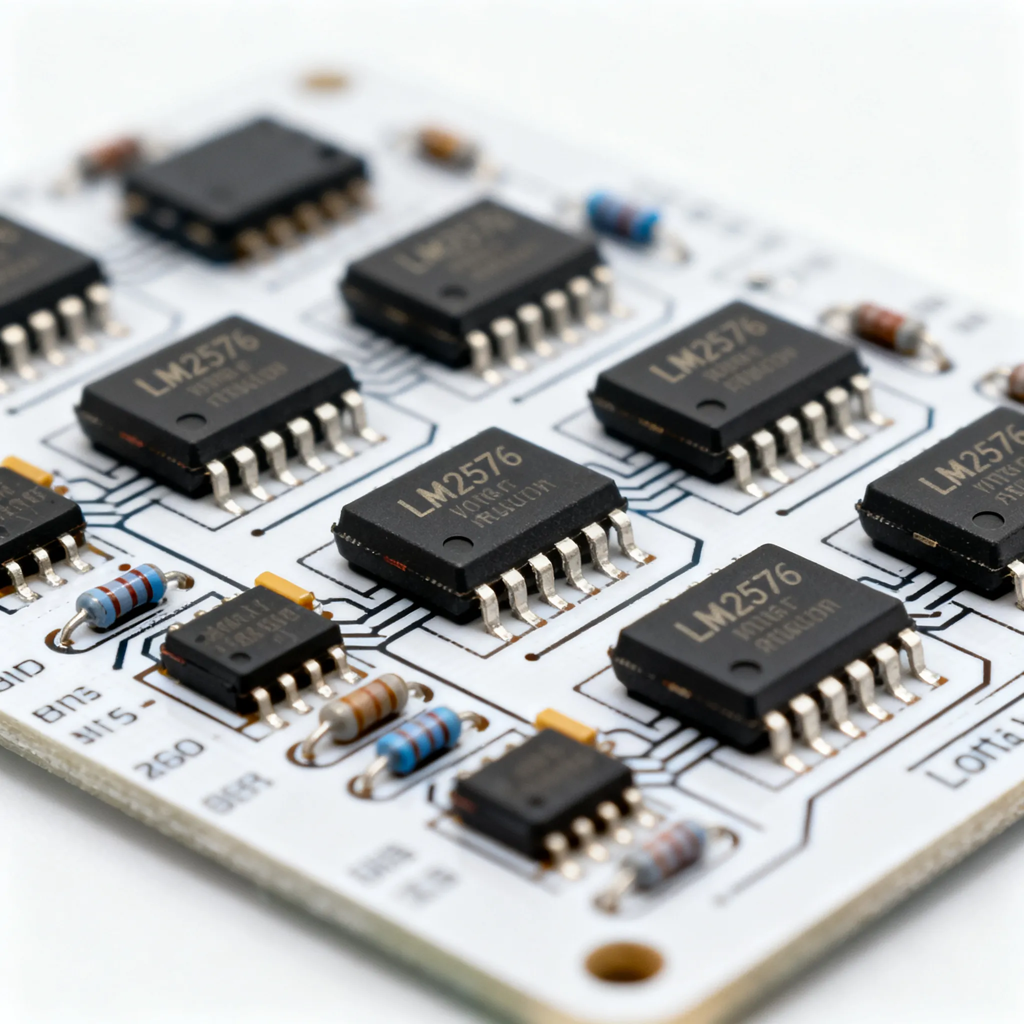
The LM2576 voltage regulator family, produced by Texas Instruments, is renowned for its simplicity and efficiency in step-down voltage regulation applications. These regulators are designed to provide all the active functions for a step-down (buck) switching regulator, capable of driving a 3A load with excellent line and load regulation. The family includes fixed output voltage options of 3.3V, 5V, 12V, 15V, and an adjustable version. Key features include a wide input voltage range of 4V to 40V, high efficiency up to 90%, and a minimal number of external components required for operation. The LM2576 is particularly suited for power supply solutions in industrial, automotive, and consumer electronics applications.
Detailed Specifications
| Parameter | Min | Typ | Max | Units | Notes |
|---|---|---|---|---|---|
| Input Voltage | 4 | - | 40 | V | Wide range for flexibility |
| Output Current | - | 3 | - | A | Continuous current capability |
| Efficiency | - | 80 | 90 | % | Efficiency under standard conditions |
| Switching Frequency | 52 | 52 | 52 | kHz | Fixed frequency operation |
| Output Voltage Tolerance | - | ±4 | - | % | Over line, load, and temperature |
| Quiescent Current | - | 5 | 10 | mA | Low standby current |
| Dropout Voltage | - | 1.4 | 1.6 | V | At 3A output current |
| Temperature Range | -40 | - | 125 | °C | Operating temperature range |
| Short Circuit Protection | Yes | - | - | - | Protection mechanism |
| Package Options | TO-220 | TO-263 | TO-263 | - | Various mounting options |
The LM2576's electrical specifications highlight its capability to handle a wide range of input voltages and deliver a consistent output current. With a fixed switching frequency, the device ensures stable performance across various applications. Its high efficiency and low quiescent current make it an ideal choice for battery-powered applications, while its robust protection features enhance reliability.
| Parameter | Value | Units | Notes |
|---|---|---|---|
| Junction-to-Ambient Thermal Resistance | 50 | °C/W | TO-220 package |
| Junction-to-Case Thermal Resistance | 3 | °C/W | TO-220 package |
| Storage Temperature Range | -65 to 150 | °C | Safe storage conditions |
| Maximum Lead Temperature | 300 | °C | For soldering, 10 seconds |
| Package Type | TO-220, TO-263 | - | Different mechanical formats |
| Weight | 1.9 | g | TO-220 package |
| Pin Count | 5 | Pins | Standard configuration |
| Mounting Style | Through Hole, Surface Mount | - | Options for different applications |
Thermal and mechanical specifications are critical for ensuring the reliability and performance of the LM2576 in various environments. The device's thermal resistance values are crucial for designing appropriate heat dissipation mechanisms, while the package type and pin configuration offer flexibility for different design requirements.
| Feature | LM2576-3.3 | LM2576-5.0 | LM2576-12 | LM2576-15 | LM2576-ADJ |
|---|---|---|---|---|---|
| Output Voltage | 3.3V | 5.0V | 12V | 15V | Adjustable |
| Efficiency (%) | 80 | 83 | 85 | 87 | Varies |
| Common Applications | Low voltage logic | General purpose | Telecom | Industrial | Custom designs |
| Additional Components | Inductor, Diode | Inductor, Diode | Inductor, Diode | Inductor, Diode | Inductor, Diode, Resistor |
| SKU | LM2576-3.3 | LM2576-5.0 | LM2576-12 | LM2576-15 | LM2576-ADJ |
The application comparison table highlights the versatility of the LM2576 family, showing how different models cater to various voltage requirements and efficiency needs. Each variant is designed to optimize performance for specific applications, with the adjustable model offering the greatest flexibility for custom designs.
Design Considerations
Designing an efficient power management system with the LM2576 requires careful consideration of several factors to optimize performance and reliability. First and foremost, selecting the appropriate model from the LM2576 family is crucial, based on the specific voltage and current requirements of the application. Engineers must also consider the thermal management aspects, as efficient heat dissipation is vital to prevent thermal shutdown and ensure longevity.
The choice of external components, such as the inductor and diode, significantly impacts the overall efficiency and stability of the system. The inductor's value influences the ripple current and transient response, while the diode's speed and voltage rating affect the switching efficiency. Selecting components with low equivalent series resistance (ESR) and high current ratings is essential for maintaining efficiency and reducing power losses.
PCB layout plays a critical role in minimizing electromagnetic interference (EMI) and ensuring stable operation. A well-designed layout with short and wide traces for high-current paths, proper grounding techniques, and adequate spacing between components helps reduce noise and improve thermal performance. Engineers should also consider incorporating features such as input and output capacitors to stabilize voltage levels and filter out high-frequency noise.
Finally, testing and validation are crucial stages in the design process. Simulating the circuit under various load conditions and environmental factors can identify potential issues and areas for improvement. Real-world testing with prototypes allows engineers to fine-tune the design, ensuring it meets the desired specifications and performs reliably in the intended application.
Step-by-Step Guide
- Define the Requirements: Determine the input voltage range, desired output voltage, and load current requirements for your application. Choose the appropriate LM2576 model that meets these criteria.
- Select External Components: Choose an inductor with the appropriate value and current rating to handle the ripple current. Select a fast-recovery diode with a voltage rating higher than the input voltage and a current rating exceeding the maximum load current.
- Design the Circuit: Refer to the LM2576 datasheet for the recommended circuit configuration. Connect the input and output capacitors, inductor, and diode as specified, ensuring proper orientation and connections.
- Layout the PCB: Design the PCB layout with careful attention to trace width, spacing, and grounding. Minimize the length of high-current paths and use wide traces to reduce resistive losses. Ensure good thermal management by providing adequate copper area for heat dissipation.
- Simulate the Circuit: Use simulation software to model the circuit's behavior under different load conditions and input voltages. Verify the stability, efficiency, and thermal performance of the design.
- Prototype and Test: Build a prototype of the designed circuit and conduct real-world testing. Measure the output voltage, efficiency, and temperature rise under various load conditions. Make adjustments as necessary to optimize performance.
- Final Validation: Conduct thorough testing to ensure the design meets all specifications and performs reliably in the intended application. Document the design and testing results for future reference and production.
- Prepare for Production: Once validated, prepare the design for mass production, considering factors such as component sourcing, assembly, and quality control processes.
Common Issues & Solutions
Designing with the LM2576 can present several challenges, but understanding common issues and their solutions can help ensure a successful implementation.
-
Issue: High Output Ripple Voltage
Solution: Use capacitors with low ESR and increase the value of the output capacitor to reduce ripple voltage. Ensure the inductor value is appropriate for the desired ripple current. -
Issue: Thermal Shutdown
Solution: Improve thermal management by using heat sinks or increasing the copper area on the PCB for heat dissipation. Ensure the device operates within its specified temperature range. -
Issue: Poor Efficiency
Solution: Verify that the external components, such as the inductor and diode, are selected for low power loss. Ensure the circuit is operating at the optimal switching frequency. -
Issue: Electromagnetic Interference (EMI)
Solution: Optimize the PCB layout to minimize loop areas and use proper grounding techniques. Consider adding EMI filters if necessary. -
Issue: Instability Under Load
Solution: Check the feedback loop and compensation network. Ensure the output capacitor value is sufficient to stabilize the voltage under dynamic load conditions.
Applications & Use Cases
The LM2576 voltage regulator family finds applications across various industries due to its versatility and efficiency. In the automotive sector, it is used for powering electronic control units (ECUs) and infotainment systems. In industrial settings, it provides reliable power for sensors, controllers, and communication devices. Consumer electronics benefit from the LM2576's compact design and low power consumption, making it suitable for portable devices, home appliances, and LED lighting systems. Its adjustable version offers flexibility for custom power solutions in prototyping and development environments.
Selection & Sourcing Guide
Selecting the right LM2576 model and sourcing quality components is crucial for a successful design. Engineers can utilize online platforms like IC Online to search for and source components with competitive pricing and fast delivery. Ensure the selected components meet the necessary specifications and are from reliable manufacturers to guarantee performance and reliability in your designs.
FAQ
-
Q: What are the main advantages of using the LM2576 voltage regulator?
A: The LM2576 offers high efficiency, a wide input voltage range, and minimal external components, making it a cost-effective and reliable solution for step-down voltage regulation. -
Q: How do I choose the right inductor for my LM2576 circuit?
A: Select an inductor with a current rating higher than the maximum load current and a value that minimizes ripple current. Refer to the datasheet for recommended values. -
Q: Can the LM2576 be used for battery-powered applications?
A: Yes, its high efficiency and low quiescent current make it suitable for battery-powered devices, extending battery life. -
Q: What precautions should I take for thermal management?
A: Ensure adequate heat dissipation through heat sinks or increased PCB copper area, and operate within the specified temperature range. -
Q: How can I reduce EMI in my LM2576 design?
A: Optimize the PCB layout, use proper grounding techniques, and consider adding EMI filters if necessary. -
Q: Is the LM2576 suitable for adjustable voltage applications?
A: Yes, the LM2576-ADJ model allows for adjustable output voltage, making it versatile for various applications. -
Q: What are the common causes of instability in LM2576 circuits?
A: Instability can be caused by insufficient output capacitance, incorrect feedback loop design, or poor PCB layout. - Q: How do I


