

Good Load Regulation The Secret to Stable Power
A stable output voltage is non-negotiable for modern electronics. Excellent load regulation is the key to achieving this sta
A stable output voltage is non-negotiable for modern electronics. Excellent load regulation is the key to achieving this stability and a constant output voltage. A regulated power supply must have good regulation.
A power supply with poor regulation exposes devices to unstable voltage, stressing components and leading to failures. This lack of regulation from the power supply is a critical fault in any design.
Proper regulation protects systems. This makes understanding load regulation essential for a reliable power supply. A well-regulated power supply with effective regulation delivers a regulated output voltage. This final regulation ensures the power supply provides a regulated, dependable voltage.
Key Takeaways
- Good load regulation keeps a power supply's output voltage steady. This happens even when the amount of power used by a device changes.
- Poor load regulation causes problems like voltage drops and spikes. These can damage electronic parts or make devices stop working.
- Engineers calculate load regulation using a formula. A lower percentage means the power supply is more stable.
- To get good load regulation, use feedback circuits and choose the right parts. Also, design the circuit board carefully with wide traces and good capacitor placement.
Understanding Load Regulation
A power supply must provide a stable voltage to the circuit it powers. The circuit's demand for current, known as the load, can change. Good load regulation ensures the output voltage remains constant even as the load fluctuates. This regulation is a critical measure of a power supply's performance. Excellent regulation is the goal for any regulated power supply.
Defining Load Regulation
Load regulation quantifies a power supply's ability to maintain its set output voltage. It measures the change in voltage from a no-load condition (minimum current) to a full-load condition (maximum current).
In simple terms, load regulation tells designers how much the output voltage will drop when the device starts drawing a lot of power. A smaller change indicates better regulation.
The required level of regulation depends on the application. A simple LED circuit might tolerate poor regulation. A sensitive microprocessor requires tight regulation to function correctly. The quality of a regulated power supply is often defined by its load regulation percentage. Different types of power supply units offer varying levels of regulation.
| Power Supply Type | Typical Load Regulation |
|---|---|
| Precision Instrumentation | ≤0.05% |
| Switching Mode Power Supplies (SMPS) | 0.05% to 0.5% |
| High-Quality Linear Regulators | ~0.1% |
| Standard (General-purpose) | 0.1% to 1% |
| Cost-sensitive Circuits | >5% |
The Formula for Calculation
Engineers calculate load regulation as a percentage. The formula compares the voltage at no load to the voltage at full load. This calculation provides a clear metric for the power supply's stability. A lower percentage signifies superior load regulation.
The formula for load regulation is:
Load Regulation (%) = [ (V_no-load - V_full-load) / V_full-load ] * 100
- V_no-load: The measured output voltage with no load connected.
- V_full-load: The measured output voltage at maximum rated current.
External factors can affect these measurements. For instance, rising temperatures increase the internal resistance of a power supply. This higher resistance causes a larger voltage drop under load, which worsens the measured load regulation. A regulated power supply must account for these variables to ensure proper regulation. This regulation is key for a stable voltage.
The Importance of Load Regulation
The importance of load regulation cannot be overstated; it is the foundation of a reliable electronic system. A power supply with poor load regulation creates an unstable environment. This instability introduces serious risks to components and system behavior. Understanding the importance of load regulation helps designers prevent critical failures. A well-regulated power supply is essential for dependable operation.
Risks in a Poorly Regulated Power Supply
A power supply with poor regulation is a direct threat to system integrity. Unstable voltage from the power supply can corrupt memory or cause microcontrollers to lock up. For example, a non-monotonic or slow-ramping voltage during startup can make a microcontroller's flash controller unstable, leading to data loss. This highlights the importance of load regulation for ensuring a predictable starting state. Proper regulation from a regulated power supply is the first line of defense against these hidden dangers.
Voltage Sag and System Instability
Voltage sag occurs when the output voltage temporarily drops as the current load increases. This dip can cause widespread system instability. A regulated device needs consistent voltage for proper function. Poor load regulation leads directly to these damaging sags.
In embedded systems, voltage sag is a common cause of unpredictable resets and crashes. A system may work under light loads but fail when high-power components like motors or transmitters activate.
This instability also affects high-speed digital circuits.
- Clock jitter, which disrupts digital timing, is directly related to power supply noise from poor regulation.
- High-speed clocks are extremely sensitive to the cleanliness of their power supply voltage.
- Computers and controllers can experience intermittent lockups or garbled data due to voltage sags.
Effective load regulation minimizes these sags, ensuring the power supply delivers a stable, regulated voltage.
Voltage Overshoot and Component Damage
Voltage overshoot is the opposite of sag. It is a brief spike in voltage that can occur when a heavy load is suddenly removed. This transient spike can be just as destructive as a sag. Many modern electronic components have very tight voltage tolerances.
Conditions outside the absolute maximum ratings may cause permanent damage to the device. Device operation at these ratings for extended periods can also have adverse effects.
Even a momentary overshoot can exceed these limits and destroy sensitive parts like CPUs and FPGAs. The following chart shows the strict maximum voltage ratings for various pins on modern FPGAs, where even a small deviation is unacceptable.
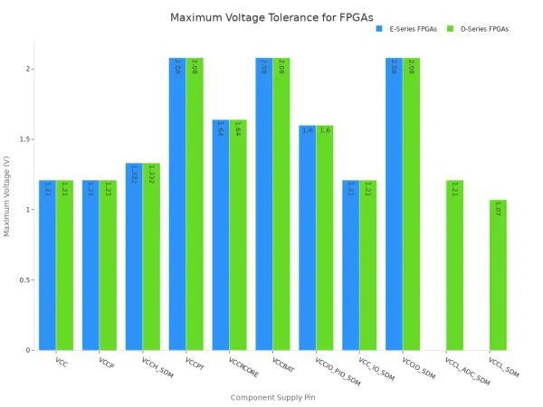
Excellent load regulation is crucial for preventing both sag and overshoot, protecting the entire system. This level of regulation defines a high-quality power supply.
Achieving Good Load Regulation in Design

Theory is important, but practical application is what creates a stable and reliable product. Achieving good load regulation requires a thoughtful approach to circuit design, component selection, and physical layout. Every choice, from the regulator IC to the width of a PCB trace, contributes to the final performance of the power supply. For complex projects, partnering with experts can be crucial. For instance, Nova Technology Company (HK) Limited, a HiSilicon-designated solutions partner, offers specialized expertise in creating stable power supply designs. This section provides actionable advice for engineers and hobbyists to build a robust regulated power supply.
The Role of Feedback Circuits
Feedback circuits are the brains behind active regulation. They constantly monitor the output voltage and make real-time corrections to keep it stable. A regulated power supply uses a negative feedback loop to maintain its setpoint. This process is the foundation of modern power regulation.
The core of this feedback system is the error amplifier. It operates based on a few fundamental principles:
- An error amplifier, a reference voltage source, and an output transistor form the internal circuit.
- The error amplifier compares a feedback voltage from the output against the stable reference voltage.
- It then adjusts the output transistor to correct any difference, ensuring a constant output voltage.
This mechanism works continuously to counteract fluctuations. The process follows a clear sequence to maintain a regulated output:
- A stable reference voltage (e.g., +2.5V) is applied to one input of the error amplifier.
- A sampled portion of the output voltage is fed to the other input.
- The error amplifier works to make the difference between its inputs zero.
- If the output voltage drops, the amplifier increases its output, telling the control element to raise the voltage.
- If the output voltage rises, the amplifier lowers its output, telling the control element to decrease the voltage.
This constant adjustment is what defines excellent regulation and is essential for good load regulation.
Component Selection for Stability
Choosing the right components is critical for achieving the desired load regulation. The voltage regulator and output capacitors are two of the most important parts of this puzzle. Their characteristics directly impact how the power supply responds to changes in load.
A designer must first choose between a linear regulator (LDO) and a switching regulator. Each has distinct trade-offs.
| Feature | LDO | Switching Regulator |
|---|---|---|
| Efficiency | Lower (40-70%) | Higher (80-95%) |
| Noise Level | Low | High |
| Thermal Stress | High | Moderate |
| PCB Complexity | Low | High |
LDOs provide a very clean, low-noise output, making them ideal for sensitive analog or RF circuits. However, they dissipate excess voltage as heat, which makes them inefficient. Switching regulators are highly efficient, making them perfect for battery-powered devices and high-current applications. Their switching action, however, generates more electrical noise.
Output capacitors also play a vital role. They act as a local reservoir of energy to handle sudden current demands.
The Equivalent Series Resistance (ESR) of an output capacitor is a critical parameter. It directly affects the stability of the power supply's control loop and the magnitude of voltage fluctuations during load changes.
Different capacitor types offer different benefits for a regulated design.
| Capacitor Type | Pros | Cons | Best Use for Load Regulation |
|---|---|---|---|
| Ceramic | Low cost, compact, good at high frequencies | Limited capacitance, can be microphonic | High-frequency decoupling right next to ICs. |
| Electrolytic | High capacitance, low cost | Larger size, shorter lifespan, polarity sensitive | Bulk energy storage to smooth low-frequency voltage changes. |
| Tantalum | Compact, stable, reliable | Can fail short with overvoltage | Stable voltage decoupling in space-constrained designs. |
Selecting the right capacitor involves balancing capacitance value, ESR, voltage rating, and cost to achieve the best possible regulation for the specific application.
Designing a Stable Regulated Power Supply
A great schematic with perfect components can still result in poor load regulation if the PCB layout is not done correctly. The physical design of the board is just as important as the electrical design. Parasitic resistance and inductance in PCB traces can undo the benefits of a well-chosen regulator.
Here are three critical PCB layout techniques for a stable, regulated power supply:
-
Use Wide Power Traces 📏 The resistance of a PCB trace causes voltage to drop as current flows through it. To minimize this drop, power traces must be wide enough for the current they carry.
The IPC-2221 standard provides formulas for calculating the necessary trace width based on current, copper thickness, and acceptable temperature rise. Using thicker copper layers also helps reduce resistance and improve load regulation.
-
Place Decoupling Capacitors Strategically 📍 Decoupling capacitors supply instantaneous current to ICs. Their effectiveness depends on their placement.
- Place capacitors as close as possible to the IC's power and ground pins. This minimizes inductance, allowing the capacitor to respond faster.
- Use multiple smaller capacitors instead of one large one for better high-frequency performance.
- Connect capacitors directly to the power and ground planes using vias placed right next to the pads.
-
Implement a Star Ground Configuration ⭐ A star ground configuration connects all ground paths to a single, central point. This technique prevents return currents from different parts of the circuit from interfering with each other. It minimizes ground noise and ensures a stable reference, which is crucial for the feedback loop's regulation accuracy.
By following these design rules, engineers can build high quality regulated power supplies that deliver stable power under all operating conditions. This careful attention to the physical design ensures the entire system benefits from good load regulation.
Good load regulation is a fundamental pillar of reliable power supply design. This regulation is not a luxury. A power supply needs this regulation. Understanding load regulation, its dangers, and its solutions is key. This regulation ensures a stable output voltage.
Investing in proper regulation for a regulated power supply saves time. A regulated power supply needs this regulation. The power supply provides a regulated, stable voltage. The power supply needs this regulation. This regulation ensures a regulated, stable voltage. The power supply needs this regulation.
FAQ
What is the difference between load and line regulation?
Load regulation measures voltage stability when the output current changes. Line regulation measures voltage stability when the input voltage changes. Both metrics are important for a stable power supply. A designer must consider both for a robust system.
Can a bad PCB layout really affect load regulation?
Yes, a bad layout directly harms load regulation. Thin traces add resistance, causing voltage drops. Poor component placement creates noise. A good PCB layout is essential for a stable power supply and is just as important as component selection.
Why is a low load regulation percentage better?
A low percentage means the output voltage changes very little. It stays close to its target value even when the load changes from minimum to maximum. This indicates a more stable and reliable power supply for sensitive electronics.
What happens if load regulation is poor?
Poor regulation causes unstable voltage. This leads to voltage sags and overshoots. These events can damage components, corrupt data, or cause system crashes. It makes an electronic device unreliable and prone to failure.


