

NCP1117DT33T5G Sourcing and Cost Optimization: A Practical Guide for Engineers
Expert guide on NCP1117DT33T5G Sourcing and Cost Optimization: A Practical Guide for Engineers. Technical specs, applications, sourcing tips for engineers and buyers.
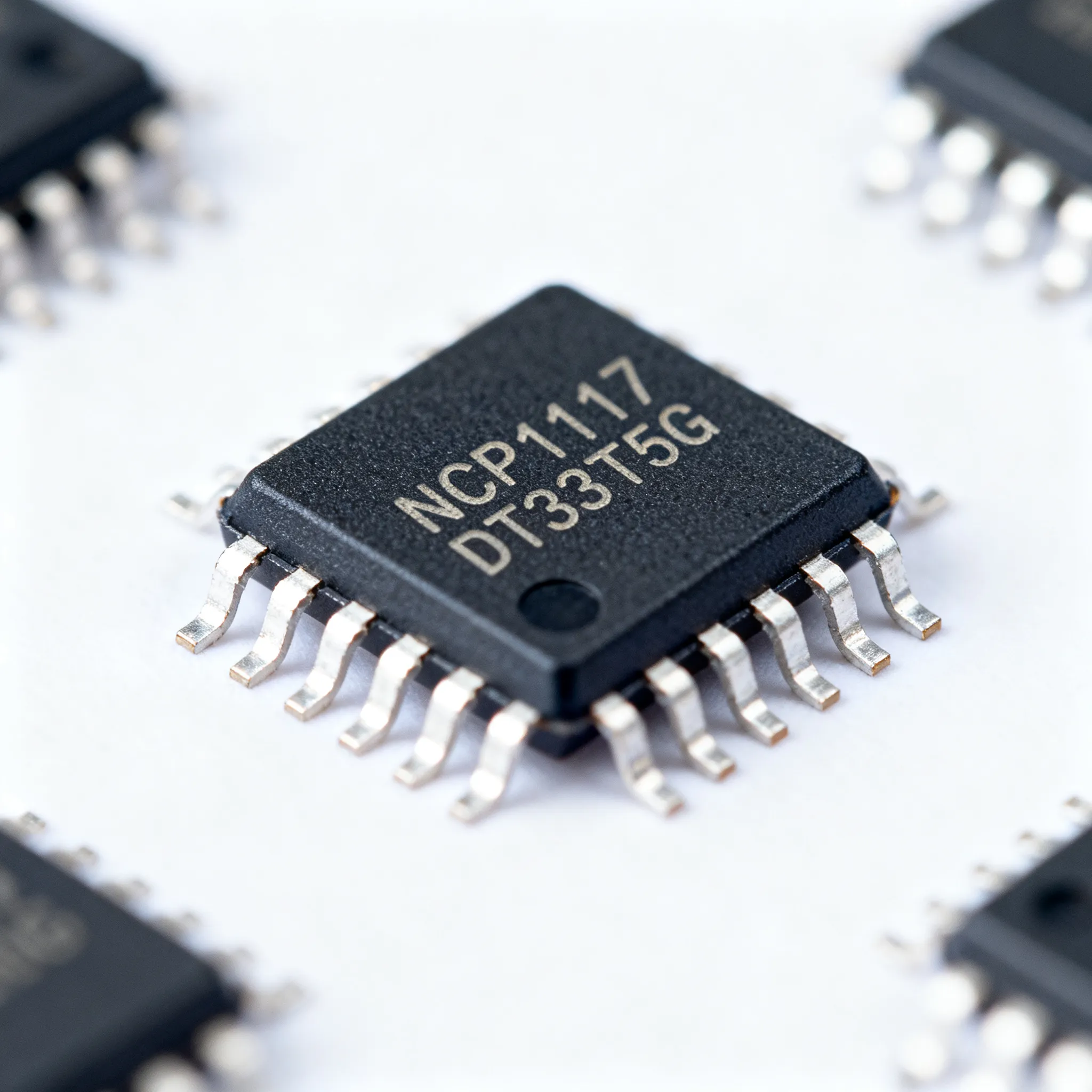
When Lead Times Stretch: The Case for Revisiting NCP1117DT33T5G Procurement
If you’ve been designing power rails for industrial controllers, IoT gateways, or motor drive auxiliaries over the last 18 months, you already know the rhythm: a familiar LDO disappears from your distributor’s shelf, the factory lead time jumps from 8 weeks to “contact us,” and your procurement team starts scrambling for spot-market stock. The NCP1117DT33T5G — ON Semiconductor’s 3.3 V, 1 A fixed-output linear regulator in a DPAK package — has not been immune to this turbulence. While it remains a workhorse in countless designs, the passive component price hikes and 16-to-24-week lead times reported across the industry in 2025–2026 are forcing engineers to treat every BoM line item as a risk variable, not a given.
Recent market signals underscore the need for a proactive procurement strategy. ON Semiconductor, like many manufacturers, has experienced allocation cycles that ripple through authorized distribution. A 2025 analysis of electronic component shortages notes that “the 2025-2026 semiconductor shortages are not solved with stockpiles but with design discipline: dual-sourcing baked into the BoM, systematic reading of PCN/PDN alerts via Octopart, SiliconExpert, and Z2Data, pin-compatible alternatives documented.” For the NCP1117DT33T5G, this means you can’t rely on a single distributor or assume that last year’s pricing will hold.
Equally important is the role of continuous supply sources when factory allocations tighten. Rochester Electronics, described as “the world’s largest continuous source of semiconductors,” lists the NCP1117DT33T5G as part of its authorized aftermarket inventory. This is not a grey-market gamble; it’s a licensed extension of the original manufacturer’s lifecycle, which can be a lifeline when standard distribution channels run dry. Additionally, the importance of recall alert systems cannot be overstated. As ScienceDirect’s overview of product recalls highlights, OEMs must maintain contact with device user facility representatives to ensure recall notifications are monitored, received, and documented. A single batch of regulators with a latent defect can trigger a field failure cascade, so tying your sourcing to traceable, authorized channels is a reliability decision, not just a cost play.
In this environment, revisiting your NCP1117DT33T5G procurement approach is not about panic-buying; it’s about building a sourcing posture that anticipates lead-time stretch, price volatility, and the occasional allocation surprise. The following sections give you the technical and commercial lenses to do exactly that.
Decoding the NCP1117DT33T5G Datasheet: Specs That Define Your Design Margins
Before you can optimize cost or qualify an alternative, you need to understand exactly what the NCP1117DT33T5G brings to your PCB. This regulator is a 1 A positive fixed-output LDO with a nominal 3.3 V output and a tight initial accuracy of ±1% over temperature. Its dropout voltage — 1.07 V typical at 1 A — is the parameter that most directly dictates your thermal budget and minimum input voltage headroom. The device is housed in a DPAK (TO-252) surface-mount package, which offers a compromise between thermal performance and board real estate, and the ‘T5G’ suffix confirms lead-free, halogen-free, and RoHS-compliant construction, essential for markets requiring environmental compliance.
Let’s put the critical numbers into a single reference table. These values are drawn from official datasheet summaries and distributor product pages, including DigiKey’s listing and All About Circuits’ datasheet aggregation.
| Parameter | Value/Range | Unit/Notes |
|---|---|---|
| Output Voltage (Fixed) | 3.3 | V; ±1% initial accuracy |
| Maximum Output Current | 1.0 | A; with adequate heatsinking |
| Dropout Voltage (VDO) | 1.07 (typ) at 1 A | V; defines minimum VIN – VOUT |
| Line Regulation | 0.2% (max) | Over full input range |
| Load Regulation | 0.4% (max) | 0 mA to 1 A |
| Quiescent Current | 6 (typ) | mA; low for a bipolar LDO |
| Ripple Rejection | 60 (typ) | dB at 120 Hz |
| Thermal Resistance (θJA) | 50 (approx., DPAK on 1 in² Cu) | °C/W; varies with layout |
| Operating Junction Temp. | −40 to +125 | °C |
| Package | DPAK (TO-252-3) | Lead-free, halogen-free (T5G) |
These numbers have immediate design consequences. The 1.07 V dropout means that if your pre-regulated rail is 5.0 V, you have about 0.63 V of headroom at full load — enough to keep the LDO in regulation even with some input ripple. However, if your input sags to 4.5 V under load, you’re dangerously close to the dropout region, where PSRR collapses and output noise climbs. The 1% accuracy spec is tight enough that you can often avoid post-regulation trimming in microcontroller and sensor supplies, but you’ll still want to account for resistor divider tolerances if you’re using the adjustable sibling.
Thermally, the DPAK’s junction-to-ambient thermal resistance of roughly 50 °C/W on a minimal copper pour means that at 1 A load with a 1.7 V input-to-output differential (e.g., 5 V to 3.3 V), you’re dissipating 1.7 W. That pushes the junction temperature to 85 °C above ambient — a 25 °C lab bench becomes 110 °C at the die, leaving only 15 °C of margin to the 125 °C maximum. In practice, you’ll need at least 1 in² of copper area dedicated to the tab to keep junction temperatures in check. The ‘T5G’ environmental suffix is not just a paperwork checkbox; it ensures compatibility with lead-free reflow profiles and avoids the tin whisker risks associated with legacy leaded finishes.
NCP1117DT33T5G vs. AMS1117-3.3 and Other LDOs: When to Switch and When to Stay
The AMS1117-3.3 is often the first alternative that pops up in parametric searches, and for good reason: it’s a 1 A, 3.3 V LDO available in SOT-223 and TO-252 packages, with a dropout voltage typically around 1.1 V. But “similar” does not mean “identical,” and a hasty substitution can lead to oscillation, thermal shutdown, or a board respin. The table below compares the NCP1117DT33T5G with two real alternatives: the AMS1117-3.3 (as detailed in IC Online’s practical guide) and the SOT-223-packaged NCP1117ST33T3G, which shares the same ON Semiconductor DNA but in a smaller footprint (Ampheo’s listing provides inventory and pricing context).
| Comparison Metric | NCP1117DT33T5G (DPAK) | AMS1117-3.3 (SOT-223 / TO-252) | NCP1117ST33T3G (SOT-223) | Selection Criteria & Failure Boundary |
|---|---|---|---|---|
| Output Voltage Accuracy | ±1% | ±1.5% (typical) | ±1% | Tighter accuracy reduces ADC reference error; AMS1117 may need calibration. |
| Dropout Voltage (1 A) | 1.07 V | 1.1 V (typ) | 1.07 V | Similar headroom; both demand careful thermal design above 0.5 A. |
| Package Thermal Resistance (θJA) | ~50 °C/W (DPAK, 1 in² Cu) | ~55 °C/W (SOT-223) / ~50 °C/W (TO-252) | ~55 °C/W (SOT-223) | DPAK dissipates heat better; SOT-223 needs more copper area for same 1 A load. |
| Stability Requirements | Stable with 10 µF tantalum or 22 µF ceramic + ESR | Requires output capacitor ESR between 0.1 Ω and 1 Ω; can oscillate with ultra-low-ESR ceramics | Same as NCP1117DT33T5G | AMS1117 ESR sensitivity is a hidden trap; always verify capacitor type. |
| Pinout | Tab = VOUT, Pin 1 = GND, Pin 2 = VOUT, Pin 3 = VIN | Varies by package; SOT-223 often Tab = VOUT, but check datasheet | Tab = VOUT, Pin 1 = GND, Pin 2 = VOUT, Pin 3 = VIN | Never assume pin compatibility; a DPAK footprint cannot accept an SOT-223 without board change. |
| Availability (2025) | 8–16 weeks lead time; stock at Digi-Key, Rochester, Heisener | Widely sourced but many second-tier brands; risk of counterfeit | Stock at Ampheo and distributors; shorter lead times possible | If board is locked to DPAK, NCP1117DT33T5G is the direct fit; if redesigning, SOT-223 saves space. |
The key takeaway from this comparison is that the NCP1117DT33T5G offers a predictable stability profile and tighter accuracy, which matters when you’re powering a 12-bit ADC or a PLL that hates supply ripple. The AMS1117-3.3 can work, but its ESR sensitivity means you must control the output capacitor’s equivalent series resistance — a detail that often gets overlooked when a junior engineer copies a reference schematic. As Ovaga’s specification comparison notes, if your hardware is already locked to the TO-252-3 (DPAK) footprint, you must stick with this model and wait for standard factory lead times; a footprint change to SOT-223 is not a drop-in move. For new designs where board space is critical, the NCP1117ST33T3G in SOT-223 delivers the same ON Semiconductor performance but demands a different layout, making it a candidate for cost-optimized, high-volume builds where every square millimeter counts.
Sourcing the NCP1117DT33T5G Without Surprises: A Buyer's and Engineer's Checklist
Procuring the NCP1117DT33T5G in today’s market is as much about risk management as it is about unit price. The days of sending a single RFQ to one distributor and closing the BoM are over. You need a multi-pronged approach that combines authorized inventory checks, lifecycle monitoring, and qualified second sources. The following checklist distills practices that procurement teams and design engineers should execute together, not in silos.
1. Map Authorized Inventory First, Then Compare. Start with ON Semiconductor’s franchised distributors. Digi-Key’s product page for the NCP1117DT33T5G shows real-time stock and pricing, and it’s backed by traceability. Rochester Electronics holds continuous inventory as a licensed source, which can be a lifesaver when factory lead times stretch beyond 16 weeks. Heisener’s listing indicates over 659,000 units in stock for the NCP1117DT33 variant, and while you must verify the exact T5G suffix, such volume suggests that the DPAK family has deep pipeline availability. Always cross-check date codes and request a certificate of conformance when buying from non-franchised sources.
2. Bake Dual-Sourcing into the BoM from Day One. Even if you never switch, having a documented, pin-compatible alternative — or at least a footprint-compatible second source — gives you leverage. For the DPAK footprint, the NCP1117DT33G (non-T5G) is a drop-in but may not meet lead-free requirements. The NCP1117ST33T3G in SOT-223 is not pin-compatible, but if you’re starting a new layout, you can design a dual-footprint pad pattern that accepts both DPAK and SOT-223 with minor routing changes. This kind of design discipline, as highlighted in AESTECHNO’s shortage mitigation guide, is what separates resilient BoMs from fragile ones.
3. Monitor PCN/PDN Alerts Religiously. ON Semiconductor issues Product Change Notifications that can affect form, fit, or function. Set up alerts on Octopart (Octopart’s NCP1117DT33G page aggregates datasheets and distributor links) and SiliconExpert to catch any die revision or material change before it impacts your production. A last-minute PCN can force a requalification cycle that costs far more than the few cents you saved on a spot buy.
4. Maintain Buffer Stock Based on Your Risk Profile. For a 1 A LDO that costs under $0.50 in volume, the carrying cost of a 12-week safety stock is negligible compared to a line-down event. The PMIC selection guide from Fly-Wing reinforces that “standard parts typically need 2-4 week lead times while custom or programmed PMICs require 6-12 weeks. Buffer stock for critical components prevents production delays.” While the NCP1117DT33T5G is a standard part, its lead time can stretch to 16 weeks during allocation, so treat it like a semi-custom item for inventory planning.
5. Verify Authenticity Before Soldering. Counterfeit LDOs are not as common as high-value FPGAs, but they exist, especially when you buy from brokers during shortages. Inspect laser markings for consistency with known good units, check date codes against factory lot numbers, and perform a simple dropout voltage test at 1 A. A genuine NCP1117DT33T5G will drop out cleanly around 1.07 V; a fake may show erratic behavior or excessive quiescent current.
To put these strategies into a quick-reference format, here’s a sourcing decision matrix that ties cost, risk, and lead time together.
| Sourcing Channel | Typical Lead Time (2025) | Cost Relative to Franchised | Authenticity Risk | Best For |
|---|---|---|---|---|
| Franchised Distributor (Digi-Key, Mouser) | 8–16 weeks (if not in stock) | Baseline | Low | Production runs, traceability requirements |
| Rochester Electronics (Authorized Aftermarket) | In stock to 4 weeks | Slightly above baseline | Low (licensed) | Bridging allocation gaps, long-lifecycle programs |
| Independent Distributor (Heisener, Ampheo) | Immediate to 2 weeks | Competitive; may offer volume discounts | Medium (verify documentation) | Prototype builds, spot buys when franchised stock is zero |
| Spot Market / Brokers | Immediate | Highly variable; can spike 3–5× | High | Emergency only; always test and inspect |
This matrix isn’t static. The 2026 passive components market update from Utmel warns that “major connector manufacturers initiated price hikes of 5% to 30% in July 2026, forcing engineers to rethink the classification and selection of industrial connectors to optimize costs.” While that report focuses on passives and connectors, the same market dynamics — raw material costs, logistics bottlenecks, and fab allocation — affect LDO pricing. Locking in a 12-month pricing agreement with a franchised distributor during a stable quarter can shield you from sudden spikes.
NCP1117DT33T5G: Questions Engineers and Buyers Ask Before Placing an Order
Over years of supporting power-management designs, certain questions about the NCP1117DT33T5G surface again and again. Here are the answers that cut through the noise.
Q: What’s the difference between NCP1117DT33T5G and NCP1117DT33G?
The ‘T5G’ suffix indicates lead-free (RoHS) and halogen-free packaging, while the ‘G’ version may be lead-containing. Always verify environmental compliance for your market. If you ship to the EU, the T5G variant is mandatory; the non-T5G part may still be available for legacy industrial applications but carries a risk of obsolescence as manufacturers phase out leaded finishes.
Q: Can I drop in an AMS1117-3.3 as a direct replacement?
Electrically they are similar, but the AMS1117-3.3 often comes in SOT-223 or TO-252, and pinouts may differ. More critically, the AMS1117 requires an output capacitor with ESR between 0.1 Ω and 1 Ω for stability; a low-ESR ceramic alone can cause oscillation. Check dropout voltage and stability requirements carefully. A PCB layout change might be needed if your board was designed for the DPAK footprint. For a detailed comparison, refer to IC Online’s AMS1117-3.3 guide.
Q: How can I spot counterfeit NCP1117DT33T5G parts?
Purchase from authorized distributors (Digi-Key, Mouser, Rochester) or use authenticated sources. Inspect laser markings: genuine ON Semiconductor parts have a consistent font, and the top mark includes a lot code that can be traced. Check date codes for plausibility — a 2025 date code on a part bought during a known allocation period is suspicious. Test dropout voltage at rated current; a genuine part will drop out cleanly at ~1.07 V. Excessive quiescent current or erratic output under load is a red flag.
Q: What are realistic lead times for NCP1117DT33T5G in 2025?
As of 2025, standard lead times range from 8 to 16 weeks depending on allocation. Some distributors like Heisener show stock available for immediate shipment, but market volatility may extend this. Always confirm with your distributor’s latest pipeline report. Rochester Electronics’ continuous source model can provide stock even when factory lead times are extended, making it a valuable buffer.
Q: Is there a smaller pin-compatible alternative to the DPAK package?
The NCP1117ST33T3G in SOT-223 offers similar performance but requires a different footprint. It is not pin-compatible with DPAK. For new designs, consider it if board space is critical; the SOT-223 package is about 40% smaller in footprint area. However, its thermal resistance is slightly higher, so you’ll need to ensure adequate copper area for heat dissipation at 1 A loads. If you’re locked into a DPAK layout, the NCP1117DT33T5G remains the direct fit.
Q: What thermal considerations should I keep in mind when drawing 1 A?
With a dropout voltage of 1.07 V at 1 A, power dissipation is ~1.07 W. Ensure adequate copper area for heat sinking; the DPAK’s thermal resistance (junction-to-ambient) is around 50 °C/W on a 1 in² copper pour, so a 1 W dissipation raises junction temperature by 50 °C above ambient. If your ambient temperature is 70 °C, the junction reaches 120 °C, leaving only 5 °C of margin to the 125 °C maximum. Derate for high ambient temperatures by reducing load current or increasing copper area. A 2 in² copper plane can lower θJA to about 40 °C/W, giving you more headroom.
References & Further Reading
Related Articles
 Blog
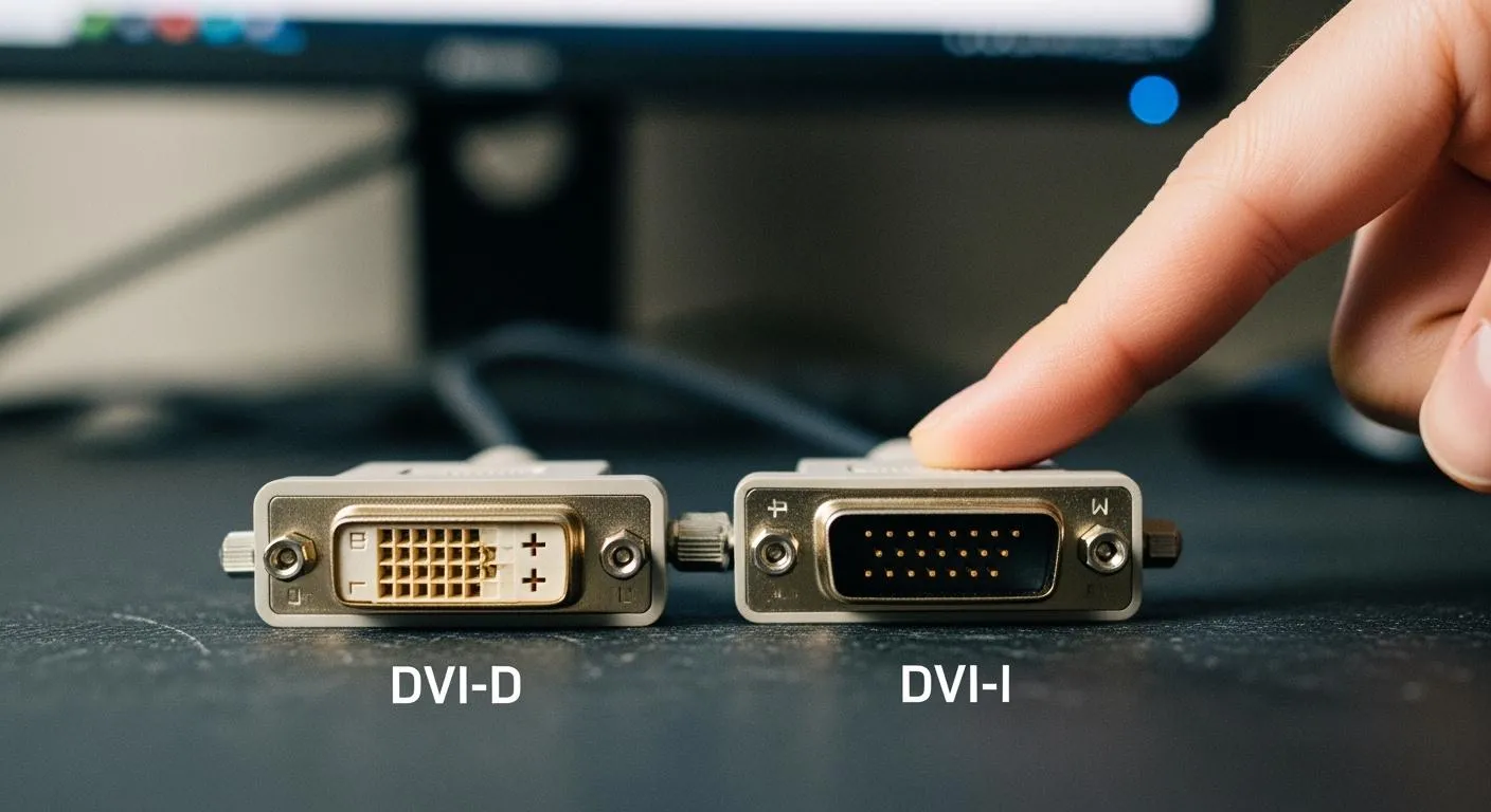
BlogDVI-D and DVI-I Which Connector Fits Your Electronics Needs
DVI-D vs DVI-I: Find out which connector suits your electronics, from modern displays to legacy industrial setups, and avoid compatibility issues.
 Blog
BlogWhat Is the Resonator and How Does It Work
A resonator in your car's exhaust system refines sound by canceling unwanted frequencies, creating a smoother, quieter driving experience.
 Blog
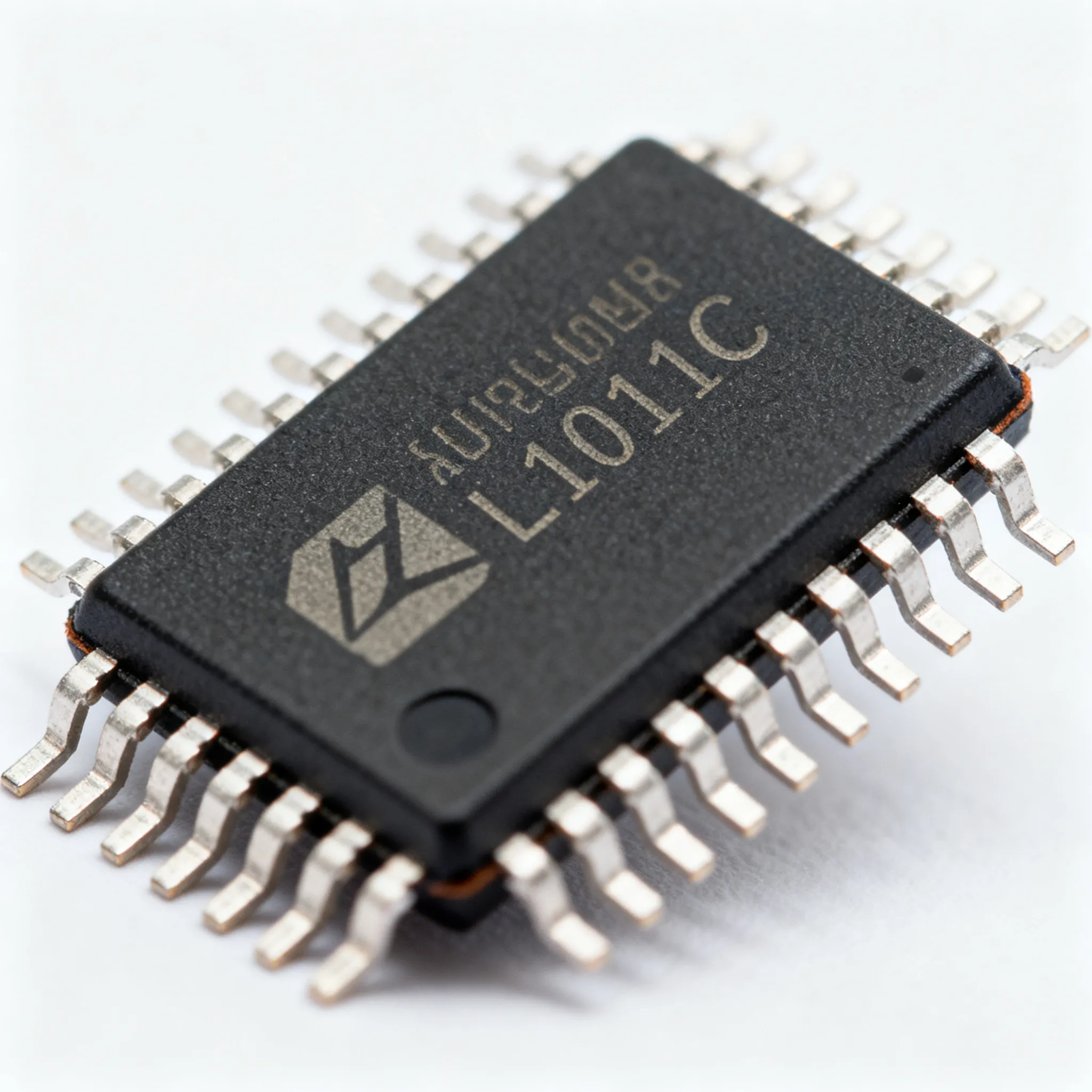
BlogStep-by-Step Design Tutorial for Implementing the L1011C in Your Circuits
Expert guide on Step-by-Step Design Tutorial for Implementing the L1011C in Your Circuits. Technical specs, applications, sourcing tips for engineers and buyers.
 Blog
BlogSelecting ESP32 or STM32 for Your Next Project
Compare esp32 vs stm32 for your project needs: wireless, power, performance, and industry fit. Find which microcontroller suits your application best.
 Blog
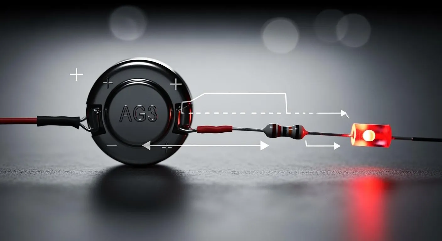
BlogUnderstanding Battery AG3 and Circuit Behavior
Battery AG3 offers stable voltage and low resistance, ensuring reliable circuit performance and longer device life in precision electronics.
 Blog
BlogWhy Nanofarad to Microfarad Matters in Modern Hardware
Nanofarad to microfarad conversion ensures accurate capacitor selection, preventing circuit errors and boosting reliability in modern electronic hardware.