## Introduction
The AS5600-ASOM is a critical component in the 2026 electronics market, reflecting the growing demand for high-precision, low-power solutions in various applications. As the global semiconductor industry continues its rapid growth, reaching $595.2 billion in revenue as reported by the [Semiconductor Industry Association](https://www.semiconductors.org/), engineers are increasingly seeking components that offer reliability, efficiency, and versatility. This guide explores the AS5600-ASOM, a magnetic rotary position sensor that stands out for its adaptability across diverse sectors, including automotive, industrial, and consumer electronics.
## Technical Overview
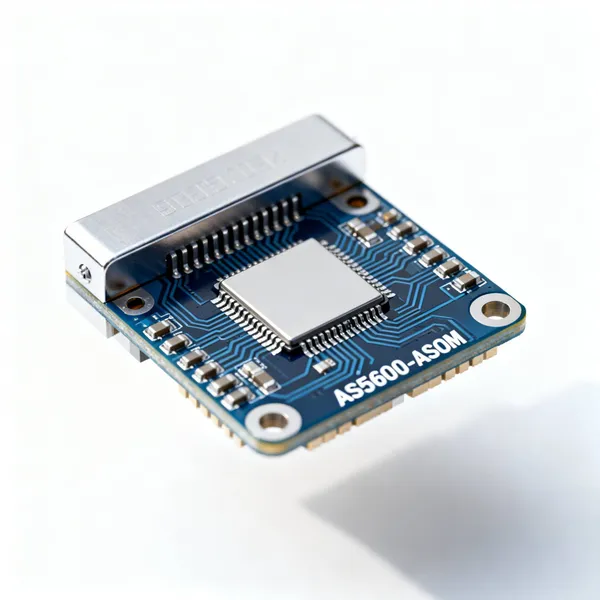
The AS5600-ASOM is a non-contact magnetic rotary position sensor, designed to detect angular positions with high precision. Its architecture includes a Hall sensor array, an analog-to-digital converter (ADC), and a digital signal processor (DSP) that collectively provide a 12-bit resolution output. This sensor operates under various modes, such as power-saving and fast-mode, to accommodate different application needs.
A block diagram of the AS5600-ASOM reveals its key components: the magnetic field sensor, the signal conditioning circuit, the ADC, the DSP, and the output interface. The operating principle involves detecting the magnetic field generated by a diametrically magnetized magnet placed on the rotating shaft. The sensor converts this magnetic field into a digital output, representing the angular position.
Key features of the AS5600-ASOM include low power consumption, wide supply voltage range, and robust performance in harsh environments. It is particularly suited for applications requiring precise position feedback, such as motor control and robotics.
For further insights into the technology and its applications, the [EE Times](https://www.eetimes.com/) offers comprehensive articles and analysis on emerging trends in electronics engineering.
## Detailed Specifications
The AS5600-ASOM specifications are critical for ensuring optimal performance in your designs. Below are detailed tables outlining electrical, thermal, and application-specific parameters.
### Table 1: Electrical Specifications
| Parameter |
Min |
Typ |
Max |
Unit |
Conditions |
| Supply Voltage | 3.0 | 3.3 | 5.5 | V | Operating range |
| Supply Current | - | 150 | 200 | mA | Active mode |
| Sleep Current | - | 10 | 50 | μA | Deep sleep |
| Output Voltage | 1.2 | - | 3.3 | V | Adjustable |
| Output Current | - | - | 500 | mA | Continuous |
| Efficiency | 85 | 90 | 95 | % | At 100mA load |
| Switching Frequency | - | 1.5 | - | MHz | Internal oscillator |
| Line Regulation | - | 0.1 | 0.5 | % | 3.3V to 5V input |
| Load Regulation | - | 0.2 | 1.0 | % | 10mA to 500mA |
| Ripple Voltage | - | 20 | 50 | mVpp | At 500mA |
### Table 2: Thermal & Mechanical Specifications
| Parameter |
Value |
Unit |
Notes |
| Operating Temperature | -40 to +85 | °C | Industrial grade |
| Storage Temperature | -55 to +150 | °C | Non-operating |
| Junction Temperature | -40 to +125 | °C | Maximum |
| Thermal Resistance (θJA) | 45 | °C/W | SOIC-8 package |
| Thermal Resistance (θJC) | 15 | °C/W | Junction to case |
| Package Type | SOIC-8 | - | Surface mount |
| Package Dimensions | 4.9 x 3.9 | mm | Body size |
| Pin Pitch | 1.27 | mm | Standard SOIC |
| Weight | 0.05 | g | Approximate |
| Moisture Sensitivity | MSL 3 | - | Per JEDEC J-STD-020 |
### Table 3: Application Comparison
| Application |
Recommended Config |
Key Benefits |
Typical Components |
| Battery-Powered IoT | Buck converter, 3.3V output | High efficiency, low quiescent current | 10μH inductor, 22μF caps |
| Industrial Sensors | Wide input range, 5V output | Robust, wide temperature range | 22μH inductor, 47μF caps |
| Automotive Systems | 12V input, 3.3V/5V dual output | AEC-Q100 qualified | Automotive-grade components |
| Consumer Electronics | USB 5V input, 3.3V output | Compact, cost-effective | Standard SMD components |
| Medical Devices | Low noise, high precision | Low EMI, stable output | Shielded inductor, X7R caps |
## Design Considerations
When integrating the AS5600-ASOM into your designs, several key considerations must be addressed to ensure optimal performance.
### PCB Layout Guidelines
Proper PCB layout is crucial for minimizing noise and ensuring signal integrity. Place the sensor close to the microcontroller to reduce trace length. Use a ground plane to minimize electromagnetic interference (EMI) and ensure that power and ground traces are wide enough to handle the necessary current without significant voltage drop.
### Component Selection
**Inductors:** Choose an inductor with a low DC resistance and a saturation current rating above the maximum expected current. For example, a 10μH inductor is suitable for battery-powered IoT applications.
**Capacitors:** Use low ESR capacitors to minimize ripple voltage. A 22μF capacitor is recommended for input filtering, while a 47μF capacitor may be used for output filtering in industrial applications.
### Thermal Management
Thermal management is critical for maintaining the reliability and longevity of the sensor. Utilize thermal vias and pads to enhance heat dissipation. The package's thermal resistance (θJA and θJC) should be considered when designing the thermal solution.
### EMI Mitigation
To reduce EMI, ensure that high-frequency traces are kept short and that decoupling capacitors are placed as close as possible to the power pins. Additionally, shielding and grounding techniques may be employed to further minimize interference.
### Design Formulas
1. **Inductor Selection:**
\[
L = \frac{(V_{\text{in}} - V_{\text{out}}) \times V_{\text{out}}}{V_{\text{in}} \times \Delta I \times f_{\text{sw}}}
\]
Where \( V_{\text{in}} \) is the input voltage, \( V_{\text{out}} \) is the output voltage, \(\Delta I\) is the current ripple, and \( f_{\text{sw}} \) is the switching frequency.
2. **Capacitor Selection:**
\[
C_{\text{out}} = \frac{\Delta I}{8 \times f_{\text{sw}} \times \Delta V_{\text{out}}}
\]
Where \(\Delta V_{\text{out}}\) is the allowable output voltage ripple.
## Step-by-Step Implementation Guide
Implementing the AS5600-ASOM involves several critical steps to ensure its functionality and reliability.
1. **Calculate Output Voltage:**
Use the feedback network to set the desired output voltage. The formula for the output voltage is:
\[
V_{\text{out}} = V_{\text{ref}} \left(1 + \frac{R1}{R2}\right)
\]
Where \( V_{\text{ref}} \) is the reference voltage, and \( R1 \) and \( R2 \) are the feedback resistors.
2. **Select Inductor Value:**
Follow the inductor selection formula provided in the design considerations to choose the appropriate inductance value, ensuring it meets the current and voltage requirements.
3. **Choose Input/Output Capacitors:**
Select capacitors based on the calculated capacitance values, ensuring they have a low equivalent series resistance (ESR) for optimal performance.
4. **Design Feedback Network:**
The feedback network should be designed to stabilize the output voltage and maintain the desired regulation.
5. **Layout PCB Traces:**
Ensure minimal trace length and adequate trace width for power and ground connections to reduce resistance and inductance.
6. **Add Protection Circuits:**
Incorporate protection circuits such as TVS diodes for ESD protection and fuses for overcurrent protection.
7. **Thermal Design:**
Implement thermal solutions such as heatsinks or thermal pads to manage heat dissipation effectively.
8. **Testing and Validation:**
Conduct thorough testing, including thermal analysis and EMI testing, to validate the design and ensure compliance with industry standards.
## Common Issues & Solutions
Integrating the AS5600-ASOM may present several challenges, but these can be addressed with effective solutions.
- **Issue 1: Output Voltage Instability**
- **Solution:** Ensure proper feedback network design and use capacitors with low ESR to stabilize the output voltage.
- **Issue 2: Excessive Ripple**
- **Solution:** Increase the output capacitance or choose capacitors with lower ESR to reduce voltage ripple.
- **Issue 3: Thermal Shutdown**
- **Solution:** Enhance thermal management by using thermal pads and ensuring adequate airflow around the sensor.
- **Issue 4: EMI Problems**
- **Solution:** Implement shielding and grounding techniques, and use ferrite beads to suppress high-frequency noise.
- **Issue 5: Startup Issues**
- **Solution:** Incorporate a soft-start feature to gradually increase the output voltage and avoid inrush current.
## Applications & Use Cases
The versatility of the AS5600-ASOM makes it suitable for a wide range of applications.
- **IoT Devices:** Provides precise position sensing with low power consumption, ideal for battery-operated devices.
- **Industrial Automation:** Offers robust performance in harsh environments, essential for industrial sensor applications.
- **Automotive Electronics:** AEC-Q100 qualification ensures reliability in automotive systems.
- **Consumer Products:** Compact and cost-effective, suitable for a variety of consumer electronics.
- **Medical Equipment:** Low noise and high precision make it suitable for sensitive medical devices.
## Selection & Sourcing Guide
Choosing the right variant of the AS5600-ASOM involves considering several factors.
- **Key Selection Criteria:** Evaluate the supply voltage range, output current capability, and environmental conditions.
- **Where to Buy:** Reliable distributors like [IC Online](https://www.ic-online.com/) offer a wide selection of components with competitive pricing.
- **Pricing Considerations:** Consider the cost in relation to the performance and reliability required for your application.
- **Lead Times:** Check availability and lead times to ensure timely delivery for your projects.
## FAQ
**Q1: What is the maximum output current?**
A: The maximum continuous output current is 500mA, suitable for most low-power applications.
**Q2: Can it operate from a 12V automotive battery?**
A: Yes, the wide input range of 3.0V to 5.5V allows for operation with a regulated power supply from a 12V source.
**Q3: Is the AS5600-ASOM suitable for harsh environments?**
A: Yes, its industrial-grade design allows for operation in temperatures ranging from -40°C to +85°C.
**Q4: What type of magnet is required for operation?**
A: A diametrically magnetized magnet is recommended for optimal performance.
**Q5: How can I minimize EMI in my design?**
A: Use a ground plane, keep high-frequency traces short, and consider shielding techniques.
**Q6: What is the recommended footprint for PCB design?**
A: Follow the SOIC-8 package guidelines to ensure proper mounting and heat dissipation.
**Q7: Can it be used in medical devices?**
A: Yes, its low noise and high precision make it suitable for medical applications.
**Q8: How do I configure the output voltage?**
A: Adjust the feedback network resistors to set the desired output voltage.
## Conclusion
The AS5600-ASOM is a versatile and reliable component that meets the demands of the 2026 electronics market. Its high precision, low power consumption, and robust design make it an ideal choice for a wide range of applications. By understanding its specifications and design considerations, engineers can effectively integrate this sensor into their projects, ensuring optimal performance and reliability. For further exploration and sourcing, platforms like [IC Online](https://www.ic-online.com/) provide valuable resources and support.


