

Choosing Your Protocol UART or SPI in 2025
You face the uart vs spi choice for your embedded project. For high-speed data transfer with devices like flash memory, choo

You face the uart vs spi choice for your embedded project. For high-speed data transfer with devices like flash memory, choose SPI. For simple communication with a single device, UART is your go-to protocol. The growth of high-speed communication protocols in embedded systems makes this decision critical. The Serial (SPI) NAND Flash market, for example, is projected to grow significantly. This article helps you select the right communication protocol for your current and future projects, ensuring your embedded systems handle data efficiently and meet modern speed demands. Understanding these protocols is key.
Key Takeaways
- Choose SPI for fast data transfer with devices like flash memory or displays.
- Use UART for simple communication with one device, like GPS modules or sensors.
- SPI needs more wires but can connect many devices efficiently.
- UART uses fewer wires but connects only two devices at a time.
- SPI works best for short distances, while UART can go longer with special parts.
Deep Dive into the SPI Protocol
The Serial Peripheral Interface (SPI) protocol is your choice for high-speed, synchronous communication. It provides fast and reliable data transfers between a master (like your microcontroller) and one or more slave devices. This protocol's main advantages come from its simple and efficient architecture.
Architecture and Speed
SPI uses a synchronous architecture for high-speed data transfer. A shared clock line (SCK) synchronizes data transmission between the master and slave. This allows for full-duplex communication, where data can be sent and received simultaneously over two separate lines:
- MOSI (Master Out, Slave In): Data from the master to the slave.
- MISO (Master In, Slave Out): Data from the slave to the master.
This design enables impressive speed. Modern microcontrollers can drive SPI at 50 MHz, while FPGAs can exceed 100 MHz. However, you must consider practical limits. The actual data transfer speed depends on factors like system latency and the size of data packets. Small, frequent data transmissions can slow down the effective rate. For example, sending larger 4KiB data blocks is more efficient than sending thousands of single bytes. Modern protocols like Quad SPI (QSPI) further boost speed by using four data lines for transmission, achieving throughput over 50 MB/s in embedded systems.
Pin Count and Complexity
A basic SPI connection requires at least four pins. This includes SCK, MOSI, MISO, and one Slave Select (SS) or Chip Select (CS) pin for each slave device. Managing multiple slaves adds complexity. You must dedicate a separate CS pin from your master to each slave device.
Firmware Tip: Your firmware needs to manage each CS line individually. You must activate only one slave at a time to prevent data corruption on the MISO line. This requires careful pin management in your code.
This approach impacts your PCB layout, as more slaves mean more traces running from the master. While this is one of the strengths and weaknesses of the SPI protocol, it ensures robust communications. An alternative is daisy-chaining, which connects slaves in a series but complicates the data transmission logic in your embedded systems.
Modern Use Cases
In 2025, you will find SPI in applications demanding high-speed data transfer. Its benefits make it ideal for performance-critical components. Common use cases for the SPI protocol include:
| Device Category | Examples | Why SPI? |
|---|---|---|
| Displays | High-framerate OLED & TFT screens | Needs high bandwidth for screen updates. |
| Memory | Fast flash memory, SD cards | Requires quick data read/write operations. |
| Wireless Modules | Wi-Fi, LoRa, and Bluetooth chips | Efficiently handles control commands and data packets. |
These applications leverage SPI for its raw speed and simple hardware-level protocol. When designing your embedded systems with these components, remember that high-speed SPI communication may require more careful power routing on your PCB to maintain signal integrity. This makes SPI one of the most powerful serial communication protocols available.
Understanding the UART Protocol
The Universal Asynchronous Receiver-Transmitter (UART) protocol is your solution for simple and reliable point-to-point serial communication. Unlike SPI, UART does not use a shared clock line. This design choice presents its own unique set of benefits and trade-offs, making it a staple in many embedded systems. The main advantages of this protocol are its ease of use and minimal wiring.
Simplicity and Wiring
UART offers great simplicity with its two-wire setup. You only need two data lines for basic transmission:
- TX (Transmit): Sends data from your device.
- RX (Receive): Receives data on your device.
This minimal pin requirement simplifies your hardware design and reduces costs. For two devices like microcontrollers to communicate, you simply cross the wires: the TX of one device connects to the RX of the other. This crossover allows both systems to send and receive data. A formal example of this is the null modem configuration.
| PC1 DB9 Pin | Signal | PC2 DB9 Pin | Signal |
|---|---|---|---|
| 2 | RD | 3 | TD |
| 3 | TD | 2 | RD |
| 5 | SGND | 5 | SGND |
Speed and Limitations
The asynchronous nature of UART is one of its defining strengths and weaknesses. Without a clock signal, both devices must agree on a transmission speed, or baud rate, beforehand. The transmission of data begins with a start bit, which tells the receiver to start listening. The receiver then uses its own internal clock to sample the incoming data.
Design Note: For a successful data transmission, the clocks of the two devices must be very close, typically within 2%. At higher speeds, even a small clock drift can cause the receiver to misread the data, leading to framing errors. This makes UART less suitable for the high-speed data transfers where SPI excels.
Common Applications
Despite its speed limitations, the UART protocol remains essential in 2025 for many embedded applications. Its simplicity and robustness make it ideal for tasks that don't require massive throughput. You will find UART in many communication protocols. This serial communication protocol is a workhorse for debugging and connecting to various modules.
| Device Category | Examples | Why UART? |
|---|---|---|
| GPS Modules | u-blox NEO-6M, NEO-7M-C-B | Provides reliable, low-speed data streams (NMEA sentences). |
| Industrial Sensors | Temperature, humidity, gas sensors | Offers a simple interface for periodic data readings. |
| Debugging | Console access in embedded Linux | Gives you direct root access to the OS for diagnostics and firmware updates. |
The ease of implementing a UART makes it one of the most dependable serial communication protocols for specific tasks in modern embedded systems.
The Core Comparison: UART vs SPI
You now understand the fundamentals of each protocol. Let's place them side-by-side to resolve the uart vs spi debate for your specific embedded project. This direct comparison will highlight the critical trade-offs between speed, complexity, and resource requirements in modern embedded systems.
Speed and Data Throughput
When your application demands high-speed data transfer, SPI is the clear winner. The synchronous clock allows it to achieve very high data rates. In contrast, UART's asynchronous nature, which relies on pre-agreed baud rates and is sensitive to clock drift, limits its maximum speed.
The difference in performance is significant. A modern microcontroller can drive SPI at speeds of 50 MHz or more, while UART typically tops out under 1 MHz. This makes SPI over 50 times faster in raw throughput.
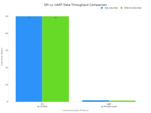
This table breaks down the performance for a high-speed transmission scenario:
| Feature | SPI (at 50 MHz) | UART (at 921600 baud) |
|---|---|---|
| Raw Data Rate | Up to 50 Mbps | 0.9216 Mbps |
| Effective Data Rate | Close to raw rate | ~0.737 Mbps (due to overhead) |
| Overhead | Minimal | ~20% (start/stop bits) |
SPI is designed for continuous, high-speed streaming. Its dedicated MOSI and MISO lines allow for true full-duplex transmission, where you can send and receive data simultaneously. While UART also has separate TX and RX lines, its protocol is better suited for intermittent, command-response style communication rather than sustained high-speed data transfer.
Device Connections
Your choice of protocol directly impacts how you connect multiple devices. The two communication protocols handle this very differently.
- SPI: You can connect many slave devices to a single SPI master. The main limitation is not the protocol itself but the number of available GPIO pins on your master device. Each slave needs a dedicated Chip Select (CS) pin. There is no hard limit, but managing more than a few slaves increases PCB complexity.
- UART: This protocol is strictly for point-to-point communication between two devices. You cannot connect a third device to the same TX/RX lines without causing data collisions.
Pro Tip: To use UART with multiple devices, you need more advanced techniques. You could implement a software-based ring bus protocol where messages are passed from one device to the next, or you could use multiple UART peripherals on your microcontroller—one for each device.
Pin Requirements
For resource-constrained embedded systems, every pin counts. The uart vs spi decision has a direct effect on your pin budget. UART offers the most benefits for pin-limited designs.
| Protocol | Pins for One Device | Pins for Three Devices |
|---|---|---|
| UART | 2 (TX, RX) | 6 (3x TX, 3x RX) |
| SPI | 4 (MOSI, MISO, SCK, CS) | 6 (MOSI, MISO, SCK, CS1, CS2, CS3) |
As you can see, UART requires a constant of two pins per connection. SPI has a higher initial cost of four pins, but it scales more efficiently. Adding a second and third slave only costs one additional pin each. If you need to connect many devices, SPI can become more pin-efficient than using multiple UART instances.
Communication Distance
The physical distance between your components is a major factor. The two protocols are designed for very different environments.
- SPI: This is a short-range protocol. It is designed for high speed communication between chips on the same PCB. Signal integrity degrades quickly over longer distances, making it unreliable for connections longer than a few inches without special driver circuits.
- UART: The basic UART signal is also for short-range use. However, you can easily extend its range with line driver ICs like RS-232 or RS-485.
Using these drivers, you can push UART communication over significant distances, making it ideal for connecting to external modules or industrial equipment.
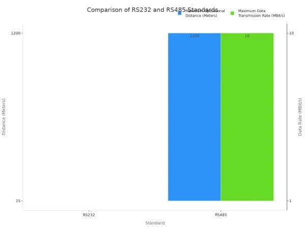
| Driver | Max Distance | Max Speed | Use Case |
|---|---|---|---|
| RS-232 | ~15 meters | ~1 Mbps | Connecting to nearby legacy equipment. |
| RS-485 | ~1,200 meters | ~10 Mbps | Multi-drop industrial sensor networks. |
Power Consumption
In battery-powered embedded devices, power is a precious resource. Both communication protocols can be used in low-power designs, but their behavior differs. Many microcontrollers allow peripherals like UART and SPI to operate or wake the system from sleep modes.
The primary difference comes from the clock.
- SPI: During an active transmission, the SCK line is constantly toggling. This switching action consumes power. For applications with frequent, high-volume data transmission, this can be a notable power draw.
- UART: Since there is no clock line, the only power consumed during transmission is from the TX line changing state. For applications that send small bursts of data infrequently, UART can be more power-efficient.
Ultimately, the total power consumption depends on your data transmission patterns. The uart vs spi choice here depends on whether your system sends data continuously or in short, periodic bursts.
Your final uart vs spi decision for your embedded project comes down to your primary need. These communication protocols serve different purposes. Choose the SPI protocol for performance-critical tasks demanding high speed with multiple peripherals. Select UART for its simplicity in point-to-point links and debugging.
Ultimately, the best of these protocols depends entirely on your embedded project's specific requirements. There is no single best communication protocol. Consider this final comparison:
| Characteristic | SPI | UART |
|---|---|---|
| Use | Fast data transfers | Simple, long-distance links |
| Complexity | Moderate (4+ wires) | Simple (2 wires) |
| Duplex | Full-duplex | Full-duplex |
These protocols offer distinct advantages. Your choice defines your system's capabilities.
FAQ
Can I use SPI and UART on the same microcontroller?
Yes, you can. Most modern microcontrollers, like those in the STM32 or ESP32 families, have dedicated hardware peripherals for both SPI and UART. You can use them at the same time to communicate with different devices. For example, you might use SPI for an SD card and UART for debugging.
Which protocol is better for battery-powered devices?
It depends on your data needs.
- UART is often more power-efficient for sending small, infrequent data bursts.
- SPI can be better if you need to transfer large data amounts quickly and then put the device back to sleep.
Your choice depends on your specific use case.
What is QSPI and how does it relate to SPI?
QSPI stands for Quad SPI. It is an enhanced version of the SPI protocol. QSPI uses four data lines instead of one (MOSI/MISO) to transfer data. This allows you to achieve much higher data throughput, making it perfect for high-density flash memory chips and fast screen updates.
Why does UART need start and stop bits?
UART is asynchronous, meaning it has no clock line. The start bit tells the receiving device that data is coming. The stop bit signals the end of the data byte. These bits help the receiver's internal clock stay synchronized for that single byte of data.


