

How a 3 Input NAND Gate Works in Digital Circuits
A 3 input nand gate lets you control digital signals in a unique way. You see output go low only when all three inputs are h

A 3 input nand gate lets you control digital signals in a unique way. You see output go low only when all three inputs are high. For every other input combination, the output stays high. This special behavior sets it apart from other logic gates.
| Logic Gate | Output Behavior for 3 Inputs | Unique Feature |
|---|---|---|
| NAND | Output is LOW only if all three inputs are HIGH; otherwise HIGH | Inversion of AND gate; output low only when all inputs are high, making it universal |
| AND | Output is HIGH only if all three inputs are HIGH; otherwise LOW | Direct AND logic without inversion |
| OR | Output is HIGH if any input is HIGH; otherwise LOW | Output depends on any input being high |
| NOR | Output is LOW if any input is HIGH; otherwise HIGH | Inversion of OR gate |
| XOR | Output depends on parity of inputs (odd number of HIGH inputs) | Sensitive to input parity |
| XNOR | Output depends on equality of inputs | Output high if inputs are equal |
Many experts consider the 3 input nand gate a universal building block in digital electronics. You can use it to create almost any logic function, which makes it practical for circuit design.
Key Takeaways
- A 3 input NAND gate outputs low only when all three inputs are high; otherwise, it outputs high.
- This gate is universal, meaning you can build any other logic function by combining NAND gates.
- Using 3 input NAND gates simplifies circuit design by reducing parts and speeding up signal processing.
- The gate’s symbol looks like an AND gate with a small circle at the output, showing it inverts the AND result.
- 3 input NAND gates save space and power in circuits, making them ideal for modern digital devices.
3 Input NAND Gate Basics
Definition
A 3 input nand gate is a digital logic gate that takes three separate input signals. You will see the output go low only when all three inputs are high. In every other case, the output stays high. This behavior matches the standard definition in digital electronics. The output is the opposite of the AND operation for three inputs. You can write this as NOT (A AND B AND C). Many integrated circuits, such as the 4023 CMOS and 7410 TTL, use this gate as a standard part. These chips often include several 3 input nand gates in one package.
Note: The 3 input nand gate is a universal gate. You can use it to build any other basic logic function.
Function
The basic operation of a 3 input nand gate depends on how you set the inputs. If any input is low, the output stays high. Only when all three inputs are high does the output switch to low. This switching happens because of the way the transistors inside the gate work. In a typical TTL version, if any input is at a low logic level, the output transistor turns off and the output floats high. When all inputs are high, the output transistor turns on and pulls the output low.
Here is a table that shows how the inputs and output relate:
| Inputs (A, B, C) | Output (Q) |
|---|---|
| 0, 0, 0 | 1 |
| 0, 0, 1 | 1 |
| 0, 1, 0 | 1 |
| 0, 1, 1 | 1 |
| 1, 0, 0 | 1 |
| 1, 0, 1 | 1 |
| 1, 1, 0 | 1 |
| 1, 1, 1 | 0 |
You can also see this behavior in a chart:
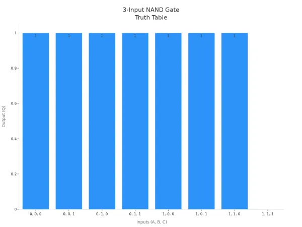
The main difference between a 3 input nand gate and a 2 input version is the number of inputs and possible combinations. A 2 input nand gate has four possible input states. A 3 input nand gate has eight. The logic stays the same: the output is high unless all inputs are high. You just have more ways to combine the inputs.
Here is how the function of a 3 input nand gate compares to other logic gates:
- The output is low only when all inputs are high. This is done by connecting transistors in series.
- For a 2 input nand gate, two transistors are used. Both must be on to pull the output low.
- If any input is low, the output stays high because the current path is not complete.
- When all inputs are high, all transistors conduct and the output goes low.
- You can add more inputs by adding more transistors in series. This increases the number of input combinations but keeps the same basic operation.
You will find that the 3 input nand gate is more reliable than some other gates in high-speed circuits. It has lower delay times and uses less space on a chip. It also has less leakage current, which helps with performance and reliability.
Truth Table and Symbol

Truth Table
You can understand how a 3 input nand gate works by looking at its truth table. The truth table lists all possible input combinations and shows the output for each one. For this gate, you have three inputs: A, B, and C. The output, Q, is high (1) for every combination except when all three inputs are high. In that case, the output drops to low (0). This pattern makes the NAND gate different from an AND gate, which only outputs high when all inputs are high.
| Inputs (A, B, C) | AND Output (A·B·C) | NAND Output Q = (A·B·C)' |
|---|---|---|
| 0, 0, 0 | 0 | 1 |
| 0, 0, 1 | 0 | 1 |
| 0, 1, 0 | 0 | 1 |
| 0, 1, 1 | 0 | 1 |
| 1, 0, 0 | 0 | 1 |
| 1, 0, 1 | 0 | 1 |
| 1, 1, 0 | 0 | 1 |
| 1, 1, 1 | 1 | 0 |
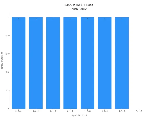
You can also see this behavior in the chart below. The output stays high for most input combinations. Only when all three inputs are high does the output go low.
Logic Symbol
When you draw a 3 input nand gate in a circuit diagram, you use a special symbol. According to IEEE and IEC standards, the symbol looks like an AND gate with a small circle, called an inversion bubble, at the output. This circle shows that the output is the opposite of the AND function. The IEEE symbol uses the classic curved shape for the AND gate, while the IEC symbol uses a rectangle. Both symbols have three input lines on the left and one output line on the right with the inversion bubble. This standard helps you recognize the gate quickly in any schematic.
Tip: Always look for the small circle at the output. It tells you the gate inverts the AND result.
Boolean Expression
You can describe the output of a 3 input nand gate using a Boolean expression. The output Q equals the negation of the AND of all three inputs. You write this as:
Q = (A · B · C)'
This means Q is high unless A, B, and C are all high at the same time. You get this expression by looking at the truth table. The AND gate outputs 1 only when all inputs are 1. The NAND gate flips this, so the output is 0 only in that case and 1 for all others.
Input and Output
Input Combinations
When you work with a 3 input nand gate, you deal with three separate inputs. Each input can be either 0 (low) or 1 (high). This setup gives you eight unique input combinations. You can see all the possible ways to set the inputs in the table below. Each row shows a different combination and the output you get from the gate.
| Input A | Input B | Input C | Output (NAND) |
|---|---|---|---|
| 0 | 0 | 0 | 1 |
| 0 | 0 | 1 | 1 |
| 0 | 1 | 0 | 1 |
| 0 | 1 | 1 | 1 |
| 1 | 0 | 0 | 1 |
| 1 | 0 | 1 | 1 |
| 1 | 1 | 0 | 1 |
| 1 | 1 | 1 | 0 |
📝 Note: You get eight combinations because each input has two possible values. The total number of combinations is 2 × 2 × 2 = 8.
Output Behavior
The output of a 3 input nand gate depends on the state of all three inputs. You will notice a clear pattern. The output stays high (1) for every combination except one. Only when you set all three inputs to high (1, 1, 1), the output drops to low (0). This behavior makes the gate useful for many digital circuits. You can use it to check if all conditions are true and then block the signal.
Take a look at the chart below. It shows how the output changes for each input combination. The output remains at 1 most of the time. It only goes to 0 when all inputs are high.

If you want to design a circuit that needs a signal to stay high unless all switches are on, the 3 input nand gate gives you a simple solution. You can rely on its output pattern to control other parts of your circuit.
Applications

Universal Gate
You can use a 3 input nand gate to build almost any logic function in digital circuits. This gate is called "universal" because you can connect its inputs and outputs in special ways to mimic other gates like AND, OR, and NOT. For example, if you tie all three inputs together, the gate acts as a NOT gate. You can also combine several 3 input nand gates to create AND or OR gates by following rules from Boolean algebra and DeMorgan's theorem. This flexibility means you do not need many different types of gates to design complex circuits.
- The output of a 3 input nand gate is 0 only when all inputs are 1. In every other case, the output is 1.
- You can use the gate as an inverter by connecting all inputs to the same signal.
- By arranging gates in certain patterns, you can build AND, OR, and other gates.
- This universal property helps you create any digital logic circuit using just nand gates.
💡 Tip: If you learn how to combine nand gates, you can design almost any digital system with fewer parts.
Circuit Design
When you use 3 input nand gates in your designs, you make circuits simpler and save space. You can combine more signals in one gate, which reduces the number of logic levels. Fewer levels mean signals travel faster through the circuit, so your design works quicker. You also avoid building deep logic trees with many 2-input gates. This helps lower propagation delay and improves speed.
| Aspect | Benefit |
|---|---|
| Fewer Logic Levels | Faster signal processing |
| Less Chip Area | Smaller, more efficient circuits |
| Universal Gate | Flexible design options |
| CMOS Efficiency | Lower power use and better performance |
In CMOS technology, you build a 3 input nand gate by connecting three NFETs in series and three PFETs in parallel. This setup makes the gate work well for inverting functions. You must watch for delays, though, because more transistors in series can slow down switching. Designers often make the NFETs larger to keep the gate fast. Using 3 input nand gates helps balance speed and size, making them a smart choice for many digital projects.
You have learned how important NAND gates are in digital circuits. These gates output low only when all inputs are high. Multi-input versions, like the three-input type, help you create complex logic with fewer parts.
- They simplify circuit design by reducing the number of gates you need.
- You can use them to build any other logic function.
- Their efficient design saves power and space in modern devices.
Keep exploring digital logic. You will find that mastering these gates opens up many possibilities in electronics.
FAQ
What does a 3 input NAND gate do?
You see the output stay high unless all three inputs are high. If every input is high, the output switches to low. This gate helps you control signals in digital circuits.
Can you build other gates using only NAND gates?
Yes, you can. You connect NAND gates in special ways to make AND, OR, and NOT gates. This makes the NAND gate a universal building block.
Why do engineers use 3 input NAND gates in circuits?
You save space and reduce the number of parts. One gate can handle three signals at once. This helps your circuit work faster and use less power.
How do you draw a 3 input NAND gate in a diagram?
You use the AND gate symbol with a small circle at the output. The circle means the output is inverted.
Tip: Always look for the bubble to spot a NAND gate.


