

How to Identify USB Connector Pinouts
You can identify a usb connector pinout by examining visual indicators and understanding the function of each pin. Quick che
You can identify a usb connector pinout by examining visual indicators and understanding the function of each pin. Quick checks help you avoid common mistakes with electronic components and integrated circuits. Look for these features:
| Indicator Type | Description |
|---|---|
| Connector Color | USB 3.0 connectors are usually blue. USB 2.0 connectors are black or white. |
| Pin Count | USB 3.0 has 9 pins. USB 2.0 has 4 pins. |
| SS Symbol | USB 3.0 cables show an 'SS' symbol. |
| Cable Thickness | USB 3.0 cables are thicker. |
Knowing the usb connector pinout keeps your devices safe and ensures efficient use.
Many beginners make these mistakes:
- Miswiring or reversed polarity
- Poor ground connections
- Bent or broken pins
- Electrical arcing or melted wires
You can avoid these issues by checking your usb connections and learning each pin’s role.
Key Takeaways
- Identify USB connectors by checking their color and pin count. USB 3.0 connectors are blue and have 9 pins, while USB 2.0 connectors are black or white with 4 pins.
- Understanding USB pinouts prevents common mistakes like miswiring and poor connections. This knowledge keeps your devices safe and ensures they work properly.
- Use pinout diagrams to troubleshoot and repair USB cables. Knowing each pin's function helps you connect devices correctly and avoid damage.
- Always check the orientation of USB connectors before plugging them in. This simple step protects your devices from damage and ensures proper connections.
- Label your USB cables after testing to avoid confusion in the future. This practice saves time and helps maintain safe electronic projects.
Why USB Connector Pinout Knowledge Matters
Preventing Errors
You need to know the usb connector pinout to keep your devices safe. When you understand how each pin works, you can avoid electrical faults. These faults can damage your electronic components or integrated circuits. You also prevent mistakes like reversed polarity or poor ground connections. Here are some ways this knowledge helps you:
- You stop electrical faults before they happen.
- You make troubleshooting easier because you know how devices connect.
- You ensure efficient usb power delivery and better data transfer.
If you use the wrong usb pinout, you risk damaging the gold plating on connectors. This can lower performance and shorten the life of your device. Exposed board fibers may wear out the socket faster than a proper connector. A tough printed connector might even harm the host device if you apply too much force.
Device Compatibility
You must match the correct usb pinout with your device to keep everything working. Different usb standards use different pin configurations. If you connect the wrong pins, your device may not get enough power or may fail to transfer data. The table below shows common problems caused by incorrect pinouts:
| Issue Type | Description |
|---|---|
| Power Delivery Issues | Incorrect pinout can disrupt power delivery, leading to insufficient power. |
| Data Transfer Problems | Wrong pinout can cause data transfer failures or corruption. |
| Device Communication Failures | Misconfigured connections can prevent devices from communicating properly. |
Matching the right usb connector pinout ensures your devices work together. You get the speed and power your devices need.
DIY and Repairs
When you repair or build electronic components, knowing the usb pinout helps you work safely. You avoid damaging integrated circuits and other parts. You can fix broken usb connectors or cables with confidence. You also make sure your repairs last longer and perform better. This knowledge gives you the tools to solve problems and improve your projects.
Identify USB Types
Visual Clues
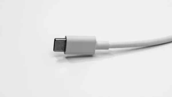
You can spot different usb types by looking at their shapes, colors, and markings. Each usb connector has a unique look that helps you tell them apart. For example, USB-A connectors are flat and rectangular, while USB-B connectors look more square with sloped corners. USB-C connectors have a small, oval, and reversible design. Mini-USB and Micro-USB connectors are smaller and have a trapezoidal shape. Color codes also help. USB 2.0 connectors often have white or black inserts, while USB 3.x connectors use blue, teal, red, or yellow inserts.
| USB Type | Visual Identification | Common Use |
|---|---|---|
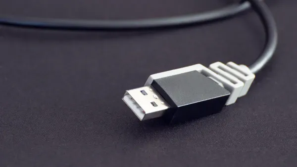
| USB-A | Flat, rectangular plug | Keyboards, mice, computers |
| USB-B | Square with beveled corners | Printers, external hard drives |
| USB-C | Small, oval, reversible | Modern phones, laptops, tablets |
| Mini-USB | Small, trapezoidal | Older cameras, MP3 players |
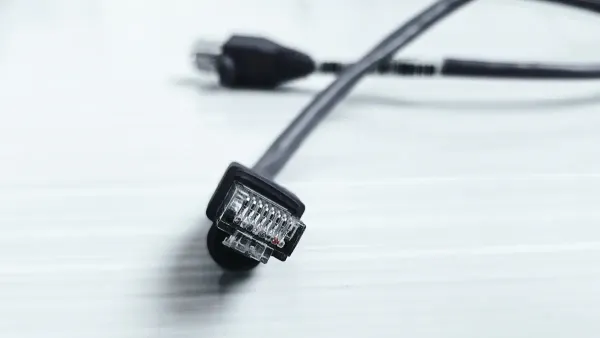
| Micro-USB | Compact, trapezoidal with wider top | Older Android phones, game controllers |
Tip: Always check the color and shape before connecting to avoid damaging your electronic components or integrated circuits.
Shape and Size
The shape and size of a usb connector give you more clues about its type and use. USB-A connectors are wide and flat, making them easy to plug into computers and other devices. USB-B connectors are more square and often used for larger devices like printers. Mini-USB and Micro-USB connectors are much smaller, designed for portable electronics. USB-C connectors are sleek, symmetrical, and can fit either way, making them popular for new devices.
| USB Type | Shape/Size Description | Common Uses |
|---|---|---|
| USB-A | Flat, rectangular | PCs, IT peripherals |
| USB-B | Square, sloped top corners | Printers, external hard drives |
| Mini-USB | Slim, snug fit | Older smartphones, cameras |
| Micro-USB | Very small, 5-pin connector | Phones, power banks, controllers |
| USB-C | Reversible, symmetrical, sleek | Modern devices, adapters |
You can use these differences to match the right usb connector pinout for your project. This helps you get the correct usb pinout for safe data transfer and usb power delivery.
Keying and Orientation
Keying and orientation features help you connect usb cables the right way. Most usb connectors have an embossed icon on the plug. This icon shows you which side should face up. USB-C connectors are reversible, so you do not need to worry about orientation. Other types, like USB-A and USB-B, only fit one way. If you try to force a connector in the wrong way, you might damage the pins or the socket. Some connectors do not have clear signs for orientation, which can make it hard to plug them in, especially in low light.
| Feature | Description |
|---|---|
| Embossed Icon | Shows correct orientation |
| Reversible Design (USB-C) | Fits both ways, prevents misconnection |
| Non-reversible Design (USB-A/B) | Only fits one way, risk of misalignment |
Note: Always check for the icon or shape before plugging in. This simple step protects your usb connector and your electronic components.
USB Connector Pinout Basics
Understanding the basics of a usb connector pinout helps you work safely with electronic components and integrated circuits. Each usb connector uses a specific arrangement of pins to manage power and data. When you know how these pins work, you can connect devices correctly and avoid damaging sensitive parts.
4-Pin Arrangement
Most standard usb connectors, like USB Type-A and USB Type-B, use a 4-pin arrangement. Each pin has a unique job. You can see how these pins work together in the table below:
| Pin Number | Name | Description |
|---|---|---|
| 1 | VBUS | Power supply (5V) |
| 2 | D- | Data transfer (negative) |
| 3 | D+ | Data transfer (positive) |
| 4 | GND | Ground |
Pin 1 (VBUS) supplies 5 volts of power to your device. Pin 4 (GND) provides the ground connection. Pins 2 (D-) and 3 (D+) handle data transfer. This setup lets the usb connector deliver both power and data at the same time. When you connect a usb cable to an electronic component or an integrated circuit, this 4-pin arrangement ensures safe and reliable operation.
Tip: Always check the pin arrangement before connecting a usb cable. This step protects your devices from short circuits and other electrical problems.
D+ and D- Data Pins
The D+ and D- pins play a key role in usb data transfer. These two pins carry information between your devices. D- (Pin 2) and D+ (Pin 3) use a method called differential signaling. This method helps reduce noise and errors during data transfer. When you connect a usb cable, the D+ and D- pins send signals in opposite directions. This design keeps your data safe from interference, which is important for electronic components and integrated circuits.
If you mix up the D+ and D- pins, your device may not work. You might see failed connections or slow data speeds. Always match the correct pins to keep your usb devices running smoothly.
Pin Functions
Each usb connector type uses a different number of pins and supports different functions. You can see the differences in the table below:
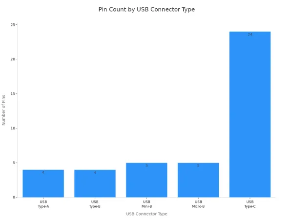
| USB Connector Type | Number of Pins | Specific Uses |
|---|---|---|
| USB Type-A | 4 (more for USB 3.0) | Universal connector for PCs, TVs, game consoles |
| USB Type-B | 4 (varies for USB 3.0) | Connects printers and external hard drives |
| USB Mini-B | 4 or 5 | Used by portable electronics like cameras and MP3 players |
| USB Micro-B | 5 (varies for USB 3.0) | Common in Android smartphones and external drives |
| USB Type-C | 24 (varies) | Supports various protocols and higher power capacities |
You can also remember the main uses for each connector:
- USB Type-A: Standard connector with 4 pins, works with most computers and TVs.
- USB Type-B: Used for printers and some external hard drives, has different versions for USB 2.0 and USB 3.0.
- USB Mini-B: Found in older cameras and MP3 players, comes in 4-pin and 5-pin versions.
- USB Micro-B: Common in smartphones and portable drives, supports both USB 2.0 and USB 3.0.
- USB Type-C: Newest connector, supports high-speed data transfer and usb power delivery, has up to 24 pins.
When you work with electronic components and integrated circuits, knowing the pin functions helps you choose the right usb connector. You can avoid mistakes and make sure your devices get the correct power and data connections. This knowledge keeps your projects safe and efficient.
USB Pinout Diagram and Layouts
Understanding the usb pinout diagram for each connector type helps you work safely with electronic components and integrated circuits. You can use these diagrams to repair, modify, or troubleshoot a usb cable. Each usb connector pinout affects how your devices communicate, transfer data, and receive power. Let’s look at the most common usb connector types and their pinout layouts.
Type-A Pinout
The type-a connector is the most familiar usb connector. You find it on computers, TVs, and many other devices. The type-a pinout uses a simple arrangement that supports both usb power delivery and usb data transmission. When you look at a usb pinout diagram for type-a, you see four main pins for USB 2.0 and nine pins for USB 3.0.
| Pin No. | Name | Description |
|---|---|---|
| 1 | 5V | 5V power supply |
| 2 | D- | Data -ve |
| 3 | D+ | Data +ve |
| 4 | Gnd | Ground |
For USB 3.0, five extra pins support faster data transfer and better power management.
| Pin No. | Name | Description |
|---|---|---|
| 1 | 5V | 5V power supply |
| 2 | D- | Data -ve |
| 3 | D+ | Data +ve |
| 4 | Gnd | Ground |
| 5 | Rx- | Receive, Shielded differential pair #1, -ve |
| 6 | Rx+ | Receive, Shielded differential pair #1, +ve |
| 7 | Gnd | Ground |
| 8 | Tx- | Transmit, Shielded differential pair #2, -ve |
| 9 | Tx+ | Transmit, Shielded differential pair #2, +ve |
You can use these pinouts to check for broken connections or to build custom usb cables for your electronic projects. The extra pins in USB 3.0 type-a connectors allow for higher data transfer speeds and improved usb power delivery, which is important for modern devices.
Type-B Pinout
The type-b connector appears on printers, scanners, and some external hard drives. The type-b pinout looks similar to type-a but uses a different shape to prevent incorrect connections. You can use the following table to identify the pinout for a type-b connector:
| Pin | Signal | Colour | Description |
|---|---|---|---|
| 1 | Vcc | Red | +5V |
| 2 | D- | White | Data- |
| 3 | D+ | Green | Data+ |
| 4 | GND | Black | Ground |
The type-b connector also supports USB 3.0 with extra pins for faster data transfer. The unique pinout configuration ensures that you do not accidentally connect a type-b cable to a type-a port, which protects your electronic components and integrated circuits from damage.
Always match the correct type-b connector with your device. This step prevents power or data errors and keeps your usb devices working safely.
Mini and Micro USB Pinout
Mini-usb and micro-usb connectors are smaller and often used in portable devices like cameras, MP3 players, and smartphones. The mini-usb connector and micro-usb connector both use a five-pin layout. This layout supports usb power delivery and allows for features like On-The-Go (OTG), which lets devices act as both host and peripheral.
| Pin Name | Function |
|---|---|
| VDD | +5V |
| D- | Data- |
| D+ | Data+ |
| ID | ID (for OTG) |
| GND | Ground |
- The ID pin in mini-usb and micro-usb connectors enables OTG functionality. This feature lets your device switch roles, which is useful for connecting two electronic components directly.
- You can use the usb pinout diagram for mini-usb and micro-usb to repair broken cables or to check for faulty connections in your integrated circuits.
Tip: Always check the pinout before soldering or repairing a mini-usb or micro-usb cable. This step helps you avoid short circuits and keeps your devices safe.
USB-C Pinout
USB-C connectors are now common in modern phones, tablets, and laptops. The usb-c pinout is more complex, with up to 24 pins. This design supports reversible connections, so you can plug in the usb cable either way. USB-C also supports much higher data transfer rates and more powerful usb power delivery.
- The usb-c connector features a reversible design, so you never have to worry about orientation.
- Multiple differential pairs in the usb-c pinout allow for data transfer speeds up to 40Gbps, which is much faster than older usb types.
- USB-C supports advanced features like video output and charging for larger devices, making it ideal for integrated circuits that need high performance.
You can use a usb pinout diagram for usb-c to troubleshoot charging issues or to design custom adapters for your electronic components.
Why Pinout Diagrams Matter
A usb pinout diagram gives you a clear map of each pin’s function. You can use these diagrams to:
- Ensure proper device functionality when building or repairing usb cables.
- Troubleshoot connection issues in electronic components and integrated circuits.
- Optimize usb data transmission and usb power delivery for your projects.
When you understand the usb connector pinout for each type, you protect your devices and improve their performance. You also make repairs and modifications much easier.
USB Standards and Pinout Differences
USB 2.0 vs 3.0 vs 4.0
You see big changes in usb pinout configurations as usb standards evolve. Each version brings new features for electronic components and integrated circuits. The table below shows the main differences in pinout and speed:
| USB Standard | Pinout Configuration | Speed |
|---|---|---|
| USB 2.0 | 4-Pin Type A/B | Up to 480 Mbps |
| USB 3.0 | 9-Pin Type A/B | Up to 5 Gbps |
| USB 4.0 | 24-Pin Type C | Up to 40 Gbps |
USB 2.0 uses a simple 4-pin layout. You find this in many older devices and basic electronic components. USB 3.0 adds five more pins, giving you faster data transfer and better power delivery. This helps integrated circuits work with high-speed signals. USB 4.0 uses a 24-pin usb pinout in the Type-C connector. You get much higher speeds and more power options. This makes USB 4.0 ideal for advanced devices and complex electronic components.
Tip: Always check the usb pinout before connecting new devices. The wrong pinout can cause problems with data or power.
Speed and Power Implications
You notice big improvements in speed and power delivery with each usb standard. USB 2.0 supports speeds up to 480 Mbps. This works for simple data tasks. USB 3.0 boosts speed to 5 Gbps. You can transfer large files quickly and power more demanding electronic components.
USB 4.0 changes the game. You get speeds up to 40 Gbps. This lets integrated circuits handle video, audio, and fast data streams. USB 4.0 also supports power delivery up to 240 watts. You can charge laptops and other powerful devices. New USB Power Delivery versions let chargers adjust voltage for better efficiency. This means your devices get the right amount of power, which protects sensitive electronic components.
Future usb standards will support even higher power outputs. You will see faster charging and better performance in many devices. Always match the usb pinout with your device’s needs. This keeps your integrated circuits safe and helps your projects run smoothly.
Note: Using the right usb pinout ensures your electronic components get the speed and power they need.
Troubleshooting USB Pinout Issues
Damaged Connectors
You may face problems with usb connections if the connectors are damaged. Damaged usb connectors can cause issues in electronic components and integrated circuits. You should check for common signs of damage before using any usb cable or port. The table below shows what to look for:
| Sign of Damage | Description |
|---|---|
| Discoloration | Changes in color on the plastic housing may show damage. |
| Cracking or Brittleness | Cracks or brittle plastic suggest the connector is weak. |
| Corrosion | Rust or white powder on metal parts means oxidation has started. |
| Reduced Contact Pressure | Gaps between contact points can cause poor usb connections. |
| Misalignment | Bent or broken pins can stop the usb from working with your devices. |
You should also inspect for discoloration, cracking, or brittleness in the plastic housing. Resistance testing helps you find environmental damage. Look for corrosion by checking metal parts and use resistance testing to confirm. Measure connection resistance to see if contact pressure is low. These steps help protect your electronic components and integrated circuits from usb failures.
Unlabeled Cables
Unlabeled usb cables can make it hard to identify the correct pinout. You need to know which wire connects to each pin, especially when working with electronic components or integrated circuits. One effective way to identify pinouts on these cables is to use a multimeter. Disconnect the usb cable at both ends. Set your multimeter to the ohms function. Check the continuity between each pin on the connector and the wires inside the cable. If the wire connects to the pin, the multimeter will show near zero ohms. This method helps you map out the usb pinout and avoid mistakes that could harm your devices.
Tip: Always label your usb cables after testing. This step saves time and keeps your electronic projects safe.
Using Tools
You can use special tools to test and identify usb pinouts with accuracy. These tools help you work safely with electronic components and integrated circuits. Some recommended tools include:
- Acroname USBHub3c: Lets you test usb-c cables in both directions with its Cable Flip feature.
- PowerJive USB meter: Measures voltage, current, and capacity with high accuracy. It does not need external batteries.
- KWS-V30 USB tester: Offers overcurrent protection and has multiple displays for easy reading.
- Klien Tools ET920: Lightweight and tests both usb type-c and usb type-a cables.
The PowerJive USB meter gives you accurate readings for voltage and current. The KWS-V30 USB tester protects your devices from overcurrent and shows clear results. The Klien Tools ET920 works for both usb type-c and usb type-a, making it useful for many projects. These tools help you find problems in usb connections and keep your electronic components and integrated circuits safe.
Note: Always use the right tool for your usb troubleshooting. This practice helps you avoid damage and ensures your devices work as expected.
You can identify usb connector pinouts by checking the connector type, counting the pins, and using diagrams for reference. Understanding usb pin functions helps you prevent errors and improves device safety, especially when working with electronic components and integrated circuits. When you use diagrams, you make troubleshooting and repairs much easier. Always follow safe connection practices and use high-quality usb cables for reliable performance.
Knowing how usb pinouts work supports better communication and power management between your devices.
For advanced usb pinout details and troubleshooting, you can explore:
- Comprehensive guides on usb pinouts
- Applications and troubleshooting tips
- Safe connection practices for usb devices
FAQ
What is a USB pinout?
A USB pinout shows you how each pin connects inside a USB connector. You use this map to link electronic components and integrated circuits safely. Pinouts help you avoid mistakes when building or repairing devices.
How do I check the pinout of an unlabeled USB cable?
You can use a multimeter to test each wire. Touch the probes to the pins and wires. This method helps you find the right connections for electronic components and integrated circuits.
Why does pinout matter for integrated circuits?
Pinout knowledge lets you connect integrated circuits without causing damage. You protect sensitive chips and ensure proper data flow. Correct pinouts keep your electronic projects working well.
Can I use any USB cable for my electronic project?
You should match the cable type and pinout to your project needs. Using the wrong pinout can harm electronic components or integrated circuits. Always check the pinout before connecting.
What tools help with USB pinout troubleshooting?
You can use USB testers, multimeters, and cable analyzers. These tools help you find faults and confirm connections in electronic components and integrated circuits. Accurate tools make your work safer and faster.


