

How to Read USB Connector Pins Diagram
When you read a usb connector pins diagram, you unlock important details for working with electronic components and integrat
When you read a usb connector pins diagram, you unlock important details for working with electronic components and integrated circuits. You must match each pin’s number to its function to avoid mistakes. Many problems in electronics come from incorrect pin identification, such as:
- Miswiring or reversed polarity
- Poor ground connections
- Bent or broken pins
- Electrical arcing or melted wires
- Unstable or floating grounds
- Frequent device disconnects
Learning to read a usb connector diagram helps you make safe connections and improve your projects.
Key Takeaways
- Understanding USB connector types is crucial. Each type has a unique shape and pin layout, affecting how you connect devices.
- Always check the pin numbering and orientation before making connections. This step prevents miswiring and potential damage to your devices.
- Familiarize yourself with the functions of each pin in a USB connector. Knowing what VCC, D+, D-, GND, and ID do helps ensure safe and effective connections.
- Use a USB pinout diagram as a reference when working on projects. This tool helps you match pins correctly and troubleshoot issues quickly.
- Follow safety precautions when handling USB connectors. Proper care prevents damage to both your devices and data.
USB Connector Types
Identifying USB Types
When you work with electronic components and integrated circuits, you often see different usb connector types. Each type has a unique shape and pin layout. Knowing these differences helps you read a usb pinout diagram and make the right connections for your projects. The USB Implementers Forum classifies the main usb connector types as follows:
| USB Connector Type | Description | Common Uses |
|---|---|---|
| Type-A | Two data pins (D+, D-) and two power pins (VCC, GND) | Computers, chargers |
| Type-B | Four pins: one power (VCC), two data (D+, D-), one ground (GND) | Printers, scanners, cameras |
| Micro USB | Similar pin configuration to Type-B, designed for compact devices | Smartphones, tablets, cameras |
| Mini USB | Similar pin configuration to Micro USB, also for compact devices | MP3 players, cameras |
You will find Type-A connectors on most computers and chargers. Type-B connectors often appear on printers and scanners. Micro USB and Mini USB are common in portable devices. Understanding these types makes it easier to match a usb pinout to the correct connector.
Visual Differences
You can identify usb connector types by their shapes and sizes. This skill is important when you design or repair electronic circuits. The table below shows the main visual features:
| USB Type | Shape/Size Description | Key Features |
|---|---|---|
| Type A | Rectangular shape, the most recognizable USB connector. | Used for general purposes, charging, and data transfer. |
| Type B | Square-shaped connector, primarily used for printers and other appliances. | Connects devices like printers to computers. |
| Mini USB | Anvil-shaped, smaller than Type A, introduced in 2005. | Used for charging mobile devices and data transfer, but considered deprecated. |
| Micro USB | Smaller than Mini USB, rounded top and flat bottom, introduced in 2007. | More durable, supports USB On The Go, and faster transfer rates. |
| Type C | Oval shape, can be plugged in either direction, smaller than Type A. | Supports simultaneous data upload/download, becoming the standard for modern devices. |
Tip: USB Type-C is quickly becoming the universal standard in consumer electronics. You see it in new smartphones, tablets, and laptops. Manufacturers prefer USB Type-C because it allows faster charging, higher data transfer speeds, and thinner device designs. By 2025, almost half of all consumer electronics will use USB Type-C connectors.
When you study a usb pinout, always check the connector type first. This step ensures you use the correct pin diagram for your electronic component or integrated circuit. Matching the right usb connector types to your project helps prevent wiring mistakes and improves device performance.
USB Connector Pins Diagram
A usb connector pins diagram gives you a clear map of how each pin in a usb connector works. You see this diagram as a table or drawing that labels every pin by number, color, and function. When you work with electronic components or integrated circuits, you need to know which pin handles power supply, which ones handle data transfer, and which pin keeps your circuit grounded. This knowledge helps you avoid mistakes and keeps your devices safe.
Pin Numbering
You find that every usb connector follows a standard pin numbering system. The numbers start from one side of the connector and go across to the other. For example, in a typical usb pinout, you see five main pins: VBUS, D-, D+, ID, and GND. Each pin has a unique job. The numbering helps you match the usb pinout diagram to the actual connector in your project.
Here is a common usb connector pins diagram for a standard USB cable:
| Pin | Name | Cable Color | Description |
|---|---|---|---|
| 1 | VCC | Red | +5 VDC power supply pin |
| 2 | D- | White | Data- pin |
| 3 | D+ | Green | Data+ pin |
| 4 | GND | Black | Ground pin |
| 5 | ID | N/A | Identification (used in some types) |
Tip: Always check the orientation of your connector before matching the pin numbers. If you reverse the numbering, you risk connecting the wrong wires, which can damage your electronic components or integrated circuits.
When you look at a usb pinout diagram, you see the pin numbers and their positions. This makes it easier to connect wires correctly and troubleshoot problems. If your device does not power on, you can check the VCC and GND pins first. If data transfer fails, you can inspect the D+ and D- pins.
Pin Functions
Each pin in a usb connector has a specific function. Understanding these roles is key when you design, repair, or troubleshoot circuits that use usb connections. Here is what each pin does in a typical usb pinout:
| Pin | Function Description |
|---|---|
| VBUS | Supplies power to the connected device through the usb port. The voltage and current depend on the usb standard and the device’s needs. |
| D+ | Sends digital signals for data transfer between devices. This pin helps move files and other information. |
| D- | Receives digital signals for data transfer. It works with D+ to make sure your data moves smoothly and reliably. |
| ID | Lets devices identify each other and decide which one acts as the host or the peripheral. You see this pin mostly in OTG (On-The-Go) cables. |
| GND | Provides a common ground for the electrical circuit. This pin keeps your circuit stable and prevents damage from voltage spikes. |
When you use a usb connector pins diagram, you can see how the pin configuration affects both power delivery and data transfer. For example, if the VBUS or GND pin is not connected properly, your device will not receive the power supply it needs. If the D+ or D- pins are damaged or miswired, your data transfer will fail or become unreliable.
Different usb connector types have unique pin configurations. Some, like USB Type-C, support higher power delivery and faster data transfer rates. Others, like Type-A, offer basic power supply and slower data transfer. Here is a quick comparison:
| USB Type | Pin Configuration Characteristics |
|---|---|
| Type-A | Standard connector for host devices, supports lower power delivery and data rates. |
| Type-B | Used for peripherals, can handle higher power delivery compared to Type-A. |
| Mini-USB | Smaller size, used in portable devices, supports moderate power and data transfer rates. |
| Micro-USB | More compact, supports faster data transfer and power delivery than Mini-USB. |
| USB-C | Reversible connector, supports the highest power delivery and data transfer rates among all types. |
Note: If your usb cable does not charge your device or transfer data, check the pin configuration. A broken or miswired pin can stop power delivery or block data transfer. Always use a usb pinout diagram to verify your connections before powering up your circuit.
A usb connector pins diagram is a vital tool for anyone working with electronic components and integrated circuits. It helps you understand how each pin supports power supply and data transfer. By learning to read a usb pinout, you can design safer circuits, fix problems faster, and get the best performance from your devices.
USB Pinout Diagram by Type
When you work with electronic components and integrated circuits, you often need to identify the correct usb pinout for your project. Each usb connector type has a unique pin configuration. Understanding these differences helps you design circuits, troubleshoot problems, and ensure safe connections. Below, you will find detailed pinout diagrams and explanations for the most common usb connectors.
USB Type A Pinout
You see usb type A connectors on most computers and chargers. This connector has a rectangular shape and four pins. You use it as the standard downstream port in many electronic devices.
| Pin Number | Name | Function |
|---|---|---|
| 1 | VCC | Power (+5V) |
| 2 | D- | Data Minus |
| 3 | D+ | Data Plus |
| 4 | GND | Ground |
- VCC supplies power to your device.
- D- and D+ handle data transfer.
- GND provides a stable ground for your circuit.
You use the usb pinout for type A when you design or repair circuits that connect to computers or power sources. The simple four-pin layout makes it easy to identify and troubleshoot connections.
USB Type B Pinout
You find usb type B connectors on printers, scanners, and some older devices. This connector has a square-like shape and also uses four pins.
| Pin Number | Name | Function |
|---|---|---|
| 1 | VCC | Power (+5V) |
| 2 | D- | Data Minus |
| 3 | D+ | Data Plus |
| 4 | GND | Ground |
- VCC powers the connected device.
- D- and D+ transfer data between your device and the host.
- GND ensures a safe and stable connection.
When you work with integrated circuits that communicate with printers or other peripherals, you use this usb pinout to match the correct pins and avoid wiring errors.
Micro USB Pinout
Micro usb connectors appear in many portable devices, such as smartphones and tablets. This connector uses five pins and supports higher data transfer speeds. It also allows for USB On-The-Go (OTG) functionality, which lets devices act as both host and peripheral.
| Pin | Name | Cable Color | Description |
|---|---|---|---|
| 1 | VCC | Red | +5 VDC |
| 2 | D- | White | Data Minus |
| 3 | D+ | Green | Data Plus |
| 4 | ID | Blue/None | Mode Detect (OTG) |
| 5 | GND | Black | Ground |
- VCC provides power.
- D- and D+ manage data transfer.
- ID pin helps your device detect OTG mode.
- GND keeps your circuit grounded.
You use the micro usb pinout when you design circuits for portable electronics or when you troubleshoot charging and data issues in small devices.
Mini USB Pinout
Mini usb connectors are smaller than type A and type B. You find them in older cameras, MP3 players, and some handheld devices. This connector also uses five pins and supports OTG.
| Pin | Name | Function |
|---|---|---|
| 1 | VCC | Power (+5V) |
| 2 | D- | Data Minus |
| 3 | D+ | Data Plus |
| 4 | ID | OTG/Mode Detect |
| 5 | GND | Ground |
- VCC powers your device.
- D- and D+ transfer data.
- ID pin enables OTG features.
- GND provides grounding.
When you work with integrated circuits in older portable devices, you use the mini usb pinout to ensure correct wiring and safe operation.
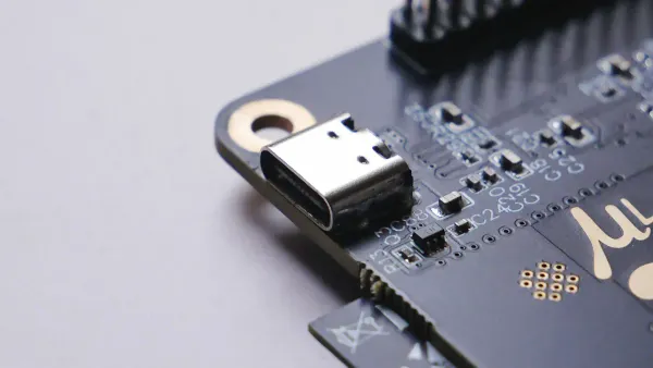
USB Type-C Pinout
The usb type-c connector is now the most advanced and versatile option. You see it in new smartphones, tablets, laptops, and many modern electronic components. The type-c connector supports the usb-c standard, which allows for high-speed data transfer, fast charging, and alternate modes like video output. The usb type-c connector has 24 pins, making it much more complex than earlier types.
| Pin Name | Function |
|---|---|
| VBUS | Power delivery (up to 240W with usb-c standard) |
| GND | Ground |
| D+ / D- | USB 2.0 data transfer, backward compatibility |
| TX1+/TX1- | SuperSpeed differential pair 1 (data transfer) |
| RX1+/RX1- | SuperSpeed differential pair 1 (data receive) |
| TX2+/TX2- | SuperSpeed differential pair 2 (data transfer) |
| RX2+/RX2- | SuperSpeed differential pair 2 (data receive) |
| CC1/CC2 | Configuration channel (orientation, power negotiation) |
| SBU1/SBU2 | Sideband use (alternate modes like DisplayPort) |
| VCONN | Cable power for active cables |
- VBUS delivers power to your device, supporting up to 240W with the usb-c standard.
- GND ensures a stable ground.
- D+ and D- allow backward compatibility with older usb devices.
- TX/RX pairs enable high-speed data transfer.
- CC1 and CC2 manage cable orientation and power negotiation.
- SBU1 and SBU2 support alternate modes, such as video output.
- VCONN powers special cables for advanced features.
You use the usb type-c pinout when you design circuits for modern devices that require fast charging, high data rates, or video output. The type-c connector’s flippable design means you do not need to worry about plug orientation, which simplifies your circuit layouts and troubleshooting.
Note: The usb type-c connector supports the usb-c standard, which allows for much higher power delivery and data transfer speeds than older connectors. You can use the same connector for charging, data, and video, making it ideal for integrated circuit design in advanced electronics.
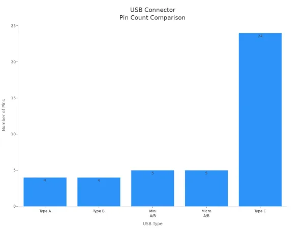
Comparing Pin Counts and Features
You can see the differences in pin counts and features across usb connector types in the table below:
| USB Type | Number of Pins | Key Features |
|---|---|---|
| Type A | 4 | Downstream connector, rectangular shape |
| Type B | 4 | Upstream connector, square-like shape |
| Mini A/B | 5 | Smaller, OTG support, used in older devices |
| Micro A/B | 5 | Thinner, higher speed, OTG support |
| Type C | 24 | Flippable, high power/data, supports usb-c standard |
You can also visualize the pin count differences here:
USB 3.0 and Legacy Pins
When you use usb 3.0 connectors, you get more pins than usb 2.0. USB 3.0 connectors have nine pins, which allow for faster data transfer. They also include legacy pins for backward compatibility. This means you can use a usb 3.0 connector with older devices that only support usb 2.0.
| USB Version | Pin Count | Functionality Description |
|---|---|---|
| USB 2.0 | 4 | Standard data transfer |
| USB 3.0 | 9 | Enhanced speed, extra pins for SuperSpeed data |
| USB Type-C | 24 | High-speed data, high power delivery, usb-c standard |
You can see the difference in pin counts in this chart:
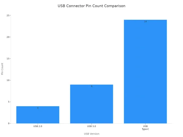
- USB 2.0 gives you basic power and data.
- USB 3.0 improves speed and power delivery.
- USB type-c supports the usb-c standard, giving you up to 240W power and the fastest data rates.
When you design or troubleshoot circuits, always check the usb pinout for your connector type. Using the correct pinout helps you avoid wiring mistakes, ensures safe operation, and lets you take full advantage of the features in modern electronic components and integrated circuits.
Reading a USB Pinout
Matching Diagram to Connector
When you work with electronic components or integrated circuits, you often need to match a usb pinout diagram to a physical usb connector. Start by identifying the type of usb connector you have. Look at the shape and pin count. Check the orientation of the connector, as this affects how you read the pin numbers. Use the color coding of the wires to help you match each pin to its function. For example, red usually means +5V, white is Data-, green is Data+, and black is Ground.
Tip: Always double-check the connector orientation before making any connections. A reversed connector can damage your circuit or device.
Common pitfalls can cause problems in your projects:
- Device not recognized: Use the correct cable and check for bent pins.
- Device not receiving power: Verify the power supply and inspect VBUS and GND connections.
- Data transfer issues: Check D+ and D- pins and look for cable damage.
Careful identification helps you avoid these mistakes and keeps your electronic components safe.
Step-by-Step Guide
Follow this process to connect a usb pinout diagram to your physical usb connector:
- Identify the usb header on your circuit board or motherboard. Most headers have 9 pins in 2 rows.
- Match each wire to the correct pin using the color code:
- Red: +5V
- White: Data -
- Green: Data +
- Black: Ground
- Align the connector with the header, making sure each wire matches the correct pin.
- Rearrange wires if needed to match the pinout or change the header connector layout.
- If your board has an NC (no connection) pin, connect the S-GND wire if required.
- For a 2x5 header, you may leave one S-GND pin unconnected.
- For a 2x4 header, the S-GND wire can also remain unconnected.
- If active pins are not in the same row, mark the wires to ensure correct pairing before connecting.
Note: Always use a usb pinout diagram as your reference. This step-by-step approach helps you make safe, reliable connections in your electronic projects.
USB Troubleshooting Tips
Common Mistakes
When you work with usb connectors in electronic components or integrated circuits, you may face several common mistakes. These errors can cause device failure, data loss, or even permanent damage. Here are some issues you should watch for:
- Misreading the usb pinout diagram. This can lead to connecting the wrong wires.
- Reversing the orientation of the usb connector. This mistake may send power to the wrong pins.
- Using a damaged or low-quality usb cable. Faulty cables often cause unreliable connections.
- Forgetting to check the power supply. Devices may not receive enough power to function.
- Unplugging a usb device during data transfer. This action can corrupt files or damage storage devices.
| Consequence | Explanation |
|---|---|
| Device Damage | Incorrect usb pinout can send high voltage to sensitive components. |
| Data Loss | Removing usb devices during transfer can corrupt files or cause data loss. |
| Flash Drive Failure | Mishandling can damage flash drives and result in lost information. |
Tip: Always double-check the usb pinout before making any connections. Careful attention helps you avoid costly mistakes in your projects.
Safety Advice
You must follow safety precautions when handling usb connectors and testing pins in your electronic circuits. These steps protect both your devices and your data:
- Encrypt local storage on devices to keep sensitive data safe.
- Prohibit unauthorized usb devices by setting strict policies and providing training.
- Disable auto-run features on computers that handle important information.
- Use a Hipot test to check insulation between power and other pins. This test helps you find faults quickly.
- Perform crush tests on connectors to ensure they can withstand pressure.
- Increase flexing test cycles to 1000 to check long-term cable reliability.
- Make sure cables are rated for their intended use.
When troubleshooting usb issues, follow these steps:
- Check the cable condition for any visible damage.
- Inspect the usb port to confirm it works properly.
- Verify the power supply to ensure the device receives enough power.
- Update device drivers to the latest version.
- Test the usb device with another computer or circuit.
Note: Always handle usb connectors with care. Never force a connector into a port. Careful handling prevents damage to both the connector and the integrated circuit.
USB Pinout Quick Reference
When you work with electronic components or integrated circuits, you often need to check a usb pinout quickly. A clear reference helps you connect devices safely and troubleshoot problems fast. You can use the following table to look up the pin functions for the most common usb connector types. This table makes it easy to match each pin to its job in your circuit.
| USB Type | Pin 1 | Pin 2 | Pin 3 | Pin 4 | Pin 5 | Extra Pins (if any) |
|---|---|---|---|---|---|---|
| Type-A | VCC (+5V) | D- | D+ | GND | — | — |
| Type-B | VCC (+5V) | D- | D+ | GND | — | — |
| Mini USB | VCC (+5V) | D- | D+ | ID | GND | — |
| Micro USB | VCC (+5V) | D- | D+ | ID | GND | — |
| Type-C | VBUS | D- / D+ | GND | CC1/CC2 | SBU1/SBU2 | TX/RX pairs, VCONN, more |
Tip: Always double-check the usb pinout before connecting wires. A mistake can damage your electronic components or integrated circuits.
You can follow some best practices to get the most out of your usb pinout quick reference:
- Use a multimeter to test each wire before you connect it to your usb circuit.
- Do not trust wire color alone. Always confirm with the usb pinout and a continuity test.
- Label each wire when you take apart a usb device. This step helps you avoid confusion during reassembly.
- Protect solder joints with heat shrink tubing to prevent shorts in your usb projects.
Here are more tips for safe and reliable usb connections:
| Best Practice | Description |
|---|---|
| Current Limitations | Never exceed the current rating of your usb power source or breadboard. |
| Short Circuits | Avoid short circuits. These can damage your usb components and breadboard. |
| Component Orientation | Check the orientation of polarized parts like diodes and capacitors. |
| Wire Management | Keep usb wires neat to prevent mistakes and accidental shorts. |
A usb pinout quick reference saves you time and helps you avoid costly errors. You can use it for any project that involves electronic components or integrated circuits. With these tables and tips, you can make safe, accurate usb connections every time.
You can interpret a usb connector pins diagram by following these steps:
- Identify each pin: VCC supplies power, D- and D+ handle data, and GND provides grounding.
- Match the diagram to your connector and check pin orientation.
- Use the quick reference table for fast lookups during circuit design or troubleshooting.
Understanding pin functions helps you prevent damage and solve problems in electronic components and integrated circuits. This knowledge lets you design safer devices and troubleshoot issues with confidence. For more on advanced topics, explore articles about USB-C technology in monitors or detailed introductions to USB standards.
FAQ
What is a USB pinout diagram used for in electronics?
A USB pinout diagram helps you connect USB ports to electronic components or integrated circuits. You use it to match each pin to its function. This prevents wiring mistakes and protects your devices.
How do I identify the correct USB connector for my circuit?
You check the shape and size of the connector. You count the pins. You compare these details to a USB pinout diagram. This helps you choose the right connector for your electronic project.
Why do some USB connectors have more pins than others?
Some USB connectors, like USB Type-C, support more features. Extra pins allow faster data transfer, higher power delivery, and special functions. You use these connectors in advanced electronic circuits and integrated systems.
Can I use any USB cable for data and power in my project?
No. Not all USB cables support both data and power. Some only charge devices. Always check the pinout and cable type before connecting to your electronic components or integrated circuits.
What should I do if my USB device does not work with my circuit?
First, check the pin connections using a USB pinout diagram.
Next, inspect the cable and connector for damage.
Finally, test the device with another circuit or port to find the problem.


