Integrated Circuit Symbols Explained for Electronics Engineers
You find integrated circuit symbols in most circuit diagrams. These symbols show how each integrated circuit links to other parts. If you know these symbols, you can read diagrams fast.
You find integrated circuit symbols in most circuit diagrams. These symbols show how each integrated circuit links to other parts. If you know these symbols, you can read diagrams fast. You can also find mistakes before they cause trouble. Symbols help you talk clearly with other engineers. They also help make sure your circuit works right. You should know what these symbols mean. You should know how to read them. You should also know how they are different from other symbols in circuit diagrams.
Key Takeaways
-
Integrated circuit symbols make circuit diagrams easier. They show whole chips as rectangles with labels and pins. - Always look at the datasheet to find the right symbol. Check the pin numbers and marks for direction before using an IC. - Watch the pin labels and marks for direction. This helps you connect ICs the right way and keeps parts safe. - Different ICs like op-amps, microcontrollers, and voltage regulators have their own symbols and pin jobs. - Use standard symbols and clear labels. This makes schematics simple to read, fix, and share with others.
Integrated Circuit Symbols Overview
What Are Integrated Circuit Symbols
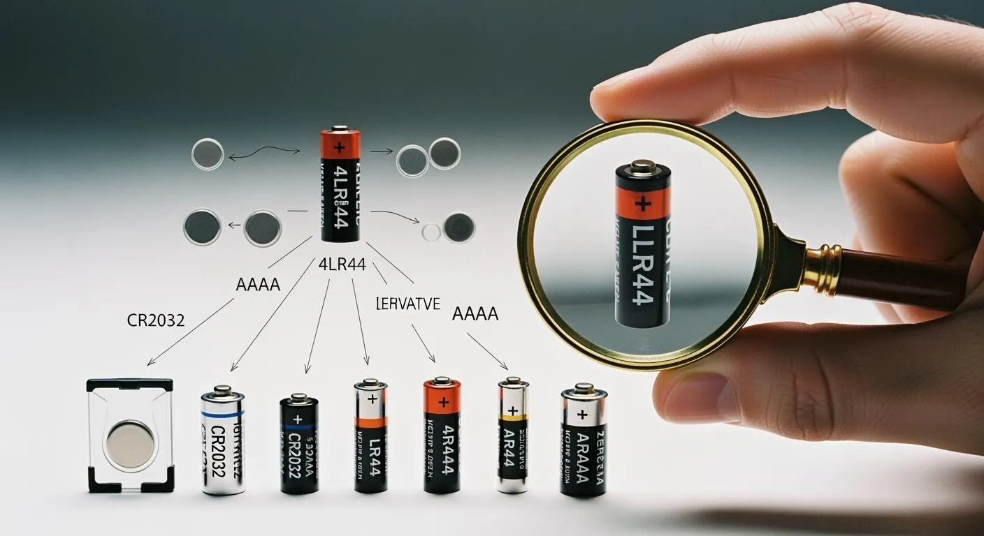
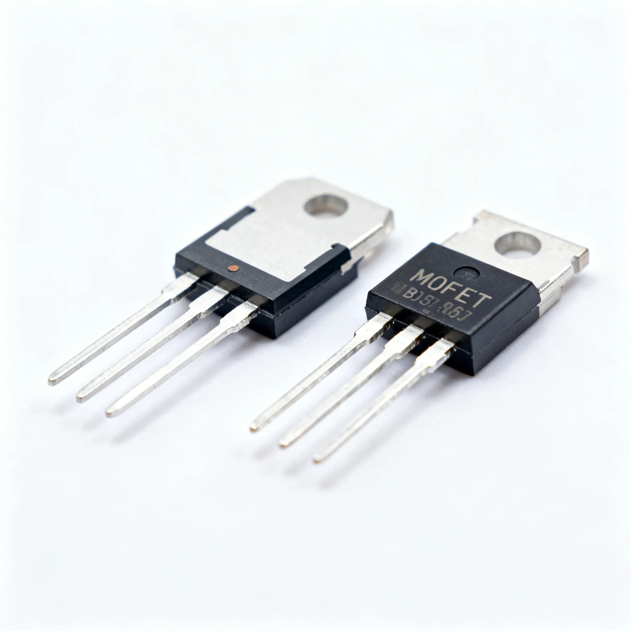
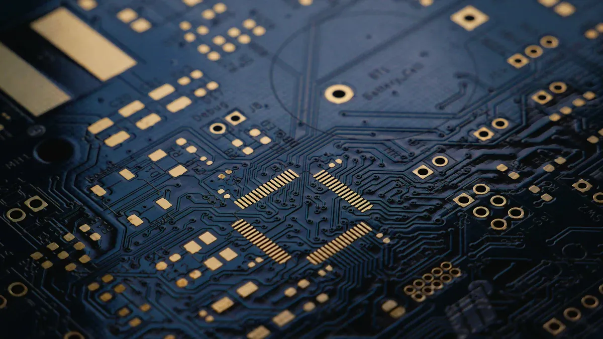
You will find integrated circuit symbols in almost every schematic. These symbols stand for ics, which are tiny chips with many electronic parts inside. Each symbol is a shortcut. You do not have to draw every part inside the chip. You just use one symbol to show the whole integrated circuit. This makes your circuit diagrams simple and clear. You can spot ics because they look like rectangles with labeled pins. These circuit symbols show you where each pin connects in the circuit. When you look at a schematic, these symbols help you see how integrated circuits fit into the bigger design.
Tip: Always look at the datasheet to find the right symbol and pinout for your ics. Sometimes, manufacturers use different layouts for similar integrated circuits.
Purpose in Circuit Diagrams
Integrated circuit symbols are very important in circuit diagrams. You use them to show how ics connect to other parts. These symbols help you avoid mistakes when you build or test a circuit. If you pick the right symbol, your circuit will work as it should. You also help other engineers understand your work. Circuit symbols for ics show what each pin does, like power, ground, input, or output. This helps you follow signals through the circuit. When you design or fix a circuit, you use these symbols to help you. They save you time and help you make fewer mistakes in your projects.
-
Integrated circuit symbols:
-
Show what each pin does
-
Help you connect ics the right way
-
Make circuit diagrams easier to read
-
Structure of IC Symbols
Rectangular Box Representation
When you look at most circuit diagrams, you will see that ICs appear as simple rectangles or boxes. This box shape helps you spot ICs quickly among other circuit symbols. The rectangle stands for the entire chip, no matter how many parts are inside. You do not need to draw every transistor or resistor inside the IC. You just use the box to show the IC as one part of your circuit.
Inside the rectangle, you will find lines that stick out from the sides. These lines show the pins of the IC. Each pin connects to a different part of your circuit. The box shape keeps your diagram neat and easy to read. You can see how the IC fits with other parts without any confusion.
Note: The rectangular box does not show what is inside the IC. It only shows how the IC connects to the rest of your circuit.
Pin Numbering and Labeling
Each pin on an IC symbol has a number and a label. The numbers help you match the pins on the symbol to the real pins on the chip. The labels tell you what each pin does. For example, you might see labels like VCC for power, GND for ground, IN for input, or OUT for output. These labels make it easy to connect the IC the right way in your circuit.
You will notice that pin numbering and labeling follow common habits, but there is no strict rule or official standard for all IC symbols. The way you number and label pins can change depending on the schematic or what your customer wants. Most engineers use clear and simple labels to avoid mistakes. Always check the datasheet for the IC you use. The datasheet will show you the correct pin numbers and what each pin does.
Here is a simple table to show how pin numbering and labeling might look for a basic IC:
|
Pin Number |
Label |
Function |
|---|---|---|
|
1 |
VCC |
Power Supply |
|
2 |
IN |
Input Signal |
|
3 |
OUT |
Output Signal |
|
4 |
GND |
Ground |
If you follow these habits, you will make your circuit diagrams much easier to read and understand.
Orientation and Polarity Markings
You must always pay attention to the orientation of IC symbols in your circuit diagrams. Most ICs have a small mark or notch on one side of the rectangle. This mark shows you which way the IC should face. If you install the IC the wrong way, your circuit will not work and you might damage the chip.
The orientation mark on the symbol matches the mark on the real IC package. You will often see a small dot or a notch near pin 1. This helps you find pin 1 quickly and connect the IC the right way. When you draw or read a circuit diagram, always look for this mark before you connect anything.
Tip: Always double-check the orientation mark before you place an IC in your circuit. This simple step can save you from costly mistakes.
Orientation and polarity markings help you avoid errors during assembly and testing. They make sure that you connect every part of your circuit in the correct way. If you follow these markings, you will build circuits that work the first time.
Types of Integrated Circuit Symbols
Op-Amps and Logic Gates
You see op-amps and logic gates in many diagrams. These ics use easy symbols that show what they do. Op-amps look like triangles with pins for input, output, and power. Logic gates, like AND, OR, and NOT, have their own shapes. Each symbol shows how signals move through the gate. You use these integrated circuits to handle signals or make choices in your design. When you look at a schematic, you can spot these ics by their shapes and pin names.
Tip: Always look at the datasheet to find the right pinout for op-amps and logic gates before you connect them.
Microcontrollers and Microprocessors
Microcontrollers and microprocessors are very important in electronics today. You use microcontrollers to control things, read sensors, and run simple code. Microprocessors do harder jobs, like running operating systems or handling lots of data. In diagrams, you see these ics as big rectangles with many pins. Each pin has a name, like power, ground, input, or output. You must watch the direction and pin numbers. Microcontrollers and microprocessors often have special pins for programming or talking to other parts. You find these integrated circuits in things like home gadgets and computers.
-
Common features of microcontrollers and microprocessors:
-
Many input and output pins
-
Power and ground pins
-
Special pins for reset or clock
-
Voltage Regulators
Voltage regulators are another key type of ics. You use them to keep voltage steady in your circuit. The symbol for a voltage regulator is a rectangle with three pins: input, output, and ground. Some integrated circuits have extra pins for control or feedback. You see voltage regulators in power supplies and battery devices. These ics keep your parts safe from voltage spikes or drops.
Note: Always use the right voltage regulator symbol for the part you have. Different ics can have different pin layouts.
Other Common ICs
You also see other types of ics in diagrams. These include timers, memory chips, and analog-to-digital converters. Each of these integrated circuits has its own symbol, but most use a rectangle with pin names. You should always read the pin names and check the datasheet for more info. These ics help you add things like timing, storage, or signal change to your designs.
|
IC Type |
Common Use |
Symbol Shape |
|---|---|---|
|
Timer |
Delays, oscillators |
Rectangle |
|
Memory |
Data storage |
Rectangle |
|
ADC/DAC |
Signal conversion |
Rectangle |
You can get good at circuit design by learning these symbols for all types of integrated circuits.
Reading IC Symbols
Identifying Pins and Functions
When you read circuit symbols for ics, you need to know what each pin does. Start by looking at the rectangle or box that represents the ic. You will see lines coming out from the sides. Each line stands for a pin. You must match these pins to the real pins on the chip.
Follow these steps to identify pins and their functions:
-
Find Pin 1: Look for a small dot or notch on the symbol. This mark shows you where pin 1 is. Always start counting from this point.
-
Read the Labels: Each pin has a label. Common labels include VCC (power), GND (ground), IN (input), and OUT (output). These labels tell you what each pin does in the circuit.
-
Check the Pin Numbers: Numbers next to the pins help you connect the right wire to the right place. Always use the datasheet to confirm the pinout.
-
Follow the Signal Flow: Trace the lines from the pins to other parts of the circuit. This helps you see how signals move through the ic.
Tip: If you ever feel unsure, compare the schematic to the physical ic. This habit helps you avoid wiring mistakes.
You will see these steps used with many common schematic symbols. Practice reading pin numbers and labels until you feel confident.
Decoding Part Numbers and Labels
Every ic has a part number. You will find this number printed on the chip and often next to the symbol in the schematic. The part number tells you the exact type of ic you need. It also helps you find the right datasheet.
Here is how you decode part numbers and labels:
-
Locate the Part Number: Look for a string of letters and numbers, such as "NE555" or "74LS00." This code identifies the ic.
-
Check the Datasheet: Use the part number to search for the datasheet online. The datasheet gives you all the details about the ic, including pin functions and electrical limits.
-
Read the Labels on the Symbol: Labels like CLK (clock), RST (reset), or EN (enable) show you special functions. These labels match the names in the datasheet.
|
Example Part Number |
IC Type |
Key Functions |
|---|---|---|
|
NE555 |
Timer |
Timing, Oscillator |
|
74LS00 |
Logic Gate |
NAND Gate |
|
LM7805 |
Voltage Regulator |
5V Output |
Note: Always double-check the part number before you order or use an ic. A small mistake can cause big problems in your circuit.
You will see part numbers and labels on many common schematic symbols. Learning to read them saves you time and prevents errors.
Recognizing Standardization in Circuit Symbols
You will notice that circuit symbols for ics look similar in most schematics. This happens because engineers follow industry standards. Standards make sure everyone uses the same shapes, labels, and pin layouts. One important standard is IPC-2612-1. This standard explains how to draw and label integrated circuit symbols.
Why does standardization matter?
-
Clear Communication: When you use standard symbols, other engineers can read your schematics without confusion.
-
Fewer Mistakes: Standard layouts help you avoid wiring errors during assembly.
-
Easy Troubleshooting: You can spot problems faster when you know what each symbol means.
Here are some features you will see in standardized circuit symbols:
-
Rectangular or box shapes for ics
-
Pin numbers and labels placed outside the box
-
Orientation marks to show pin 1
-
Consistent use of common schematic symbols for power, ground, and signals
Alert: Not every schematic follows the standard perfectly. Always check the legend or notes on the diagram for special symbols.
You should learn the main standards for circuit symbols. This skill helps you read and draw schematics that work for any project.
IC Symbols vs. Other Circuit Symbols
Differences from Discrete Components
When you look at a schematic, you see many symbols. IC symbols are not the same as symbols for discrete components. Discrete components are things like resistors, capacitors, diodes, and transistors. These parts use simple shapes, such as zigzags or arrows. You can spot them fast because each has its own symbol.
IC symbols look like rectangles or boxes with lots of pins. Each pin connects to a different part of the circuit. Discrete components usually have only two or three pins. IC symbols often have many more pins than that. This makes it easy to find ICs when you look at a diagram.
Note: Discrete components show just one job, like resistance or capacitance. IC symbols show a whole chip that can do many jobs inside.
Visual and Functional Distinctions
You can tell IC symbols from other symbols by their shape and details. IC symbols use a box shape with names on the pins. Discrete components use lines, curves, or arrows instead. This makes your circuit diagrams easier to read and understand.
IC symbols and discrete components also work differently. Discrete components do only one thing in the circuit. IC symbols stand for chips that can do many things at once. For example, an op-amp IC can make signals bigger, but a resistor only slows down current. You use circuit symbols to show how each part fits in the circuit. When you see a box with lots of pins, you know it is an IC symbol.
Here is a quick comparison:
|
Feature |
IC Symbols |
Discrete Component Symbols |
|---|---|---|
|
Shape |
Rectangle/Box |
Lines, Zigzags, Arrows |
|
Pin Count |
Many |
Few (2-3) |
|
Function |
Multiple |
Single |
Tip: Always check the legend on your schematic. Some symbols may look alike, but they can do very different things in the circuit.
Using IC Symbols in Circuit Design
Best Practices for Schematic Reading
When you look at a schematic, you should find IC symbols fast. These symbols look like rectangles with pins that have numbers and names. Always read the names and values on the diagram. These details help you know which IC is in your circuit. Some ICs, like op-amps or voltage regulators, have special symbols for their pin layouts.
Here are some good habits for reading schematics:
-
Find dots where wires cross. These dots mean the wires connect. This helps you not make mistakes.
-
Use net names instead of drawing every wire. This keeps your diagram simple and neat.
-
Make sure each IC has its own name or number. This helps you find parts when you build or fix the circuit.
-
Read the labels and values next to each symbol. These tell you what each part does.
Tip: Start by looking for inputs on the left and outputs on the right. This makes it easier to see how the circuit works.
Drawing and Labeling ICs
When you draw IC symbols, keep your diagrams tidy and clear. Use the same symbol for the same kind of device. Follow rules like IEEE or IEC so others do not get confused. Put text labels and values in the same way for every symbol. This makes your diagram easier to read.
Draw power at the top and ground at the bottom of your schematic. Put parts that work together in groups or on different pages if your circuit is big. Give each IC its own name or number. Add a title block with the circuit name, your name, date, and version. Draw decoupling capacitors close to their ICs to show they go together.
|
Drawing Tip |
Why It Matters |
|---|---|
|
Consistent symbols |
Reduces confusion |
|
Unique designators |
Eases identification |
|
Logical arrangement |
Improves understanding |
Troubleshooting with Circuit Symbols
When you fix a circuit, IC symbols help you find the right places to check. You can follow signals from input to output by looking at the labeled pins. If something is wrong, check the pin numbers and names on the symbol. This helps you find wiring mistakes or wrong connections quickly.
Split big circuits into smaller groups. This makes it easier to find problems. Always compare the diagram to the real circuit. Look for missing dots or mixed-up labels. Small mistakes like these can cause big trouble.
Alert: Always check the orientation marks on IC symbols. If you put an IC in backwards, your circuit will not work.
Learning Circuit Symbols
Tips for Electronics Engineers
You can master learning circuit symbols with the right approach. Start by studying real schematics. Look for different circuit symbols and see how they connect. Practice drawing each symbol by hand. This helps you remember the shapes and pin layouts. Use flashcards to test yourself on what each symbol means.
Join online forums or groups where engineers share circuit diagrams. Ask questions if you do not understand a symbol. Many engineers learn best by working on real projects. Build simple circuits and match each part to its symbol. Over time, you will spot patterns and remember the details.
Tip: Keep a notebook of new symbols you find. Write down the function of each symbol and the type of circuit where you saw it.
You can also use simulation software. These tools let you build circuits on your computer. You can see how each symbol works in a real circuit. This hands-on practice makes learning circuit symbols much easier.
Common Mistakes to Avoid
You may face some common mistakes when learning circuit symbols. One mistake is mixing up similar symbols. For example, you might confuse a voltage regulator with an op-amp. Always check the pin labels and orientation marks.
Another mistake is ignoring the datasheet. If you skip this step, you might connect the circuit wrong. Always match the symbol to the real part before you build the circuit.
|
Mistake |
How to Avoid |
|---|---|
|
Wrong pin connection |
Double-check pin numbers |
|
Ignoring orientation |
Look for notches or dots |
|
Skipping datasheets |
Always review before wiring |
Alert: Never guess a symbol’s meaning. If you are unsure, look it up or ask an expert. This habit keeps your circuit safe and working.
By staying alert and practicing often, you will avoid these mistakes. Learning circuit symbols takes time, but you will get better with each new circuit you study.
Learning integrated circuit symbols helps you build circuits better. You can read diagrams quickly and find mistakes early. Knowing these symbols makes you feel sure and helps you do your work right.
-
Check datasheets many times.
-
Learn rules like IPC-2612-1.
-
Try drawing and reading real diagrams.
Tip: Use websites, books, and computer tools to keep learning.
FAQ
What should you do if you cannot find the exact IC symbol in your schematic software?
You should check the datasheet for the pinout. Use a generic rectangle symbol and label each pin clearly. Add notes for special functions. This method keeps your schematic accurate and easy to read.
How can you quickly identify pin 1 on an IC symbol?
Look for a small dot or notch on the symbol. This mark always shows pin 1. You should match this mark with the real IC before you connect anything.
Why do some IC symbols have more pins than the physical chip?
Some symbols show extra pins for optional features or future upgrades. Always compare the symbol with the datasheet. This step helps you avoid wiring mistakes.
Can you use the same IC symbol for different chips?
No, you should not use the same symbol for different chips. Each IC has a unique pinout and function. Always use the correct symbol and label for each part.
What is the best way to avoid mistakes when reading IC symbols?
Tip: Always double-check the pin numbers and labels with the datasheet. Mark the orientation on your schematic. Careful checking helps you avoid costly errors.