

Mastering the 10K Sensor Chart for Reliable Results
Accurate temperature measurement helps you achieve reliable results in electronic projects. The 10k sensor chart guides you

Accurate temperature measurement helps you achieve reliable results in electronic projects. The 10k sensor chart guides you when you use a temperature sensor for precise control. You can avoid common errors such as thermal load, calibration uncertainties, and curve fit error.
- Common sources of error in temperature sensing solutions:
- Sensor geometry
- Resolution
- Thermal stability
- Hysteresis
Understanding the temperature versus resistance relationship improves measurement accuracy.
| Evidence | Explanation |
|---|---|
| Use of RTDs | RTDs have predictable resistance changes with temperature, enhancing accuracy. |
| Four-wire RTDs | They eliminate lead wire errors, improving precision. |
| Higher resistance sensors | Switching to higher resistance sensors refines accuracy. |
Key Takeaways
- Accurate temperature measurement is crucial for reliable results in electronic projects. Use the 10k sensor chart to avoid common errors.
- The 10k ohm NTC thermistor is a cost-effective and sensitive option for temperature sensing. It provides fast response times and high accuracy.
- Always calibrate your thermistor to ensure accurate readings. Use reference points and average multiple readings for best results.
- Follow best practices for setup, including using a four-wire measurement technique and ensuring good thermal contact for reliable performance.
- Regularly check and maintain your sensor to prevent issues like self-heating and lead resistance, ensuring consistent temperature measurements.
10k Ohm NTC Thermistor Basics
Temperature Sensor Overview
You often use a 10k ohm ntc thermistor as a temperature sensor in electronic circuits. This sensor helps you measure temperature changes with high sensitivity. The ntc thermistor works by changing its resistance as the temperature changes. When the temperature rises, the resistance of the ntc thermistor drops. When the temperature falls, the resistance increases. This property makes the ntc thermistor a popular choice for temperature sensor applications in HVAC systems, industrial controls, and consumer electronics.
You will find that the ntc thermistor responds quickly to temperature changes. This fast response time gives you more accurate and timely readings than many other temperature sensor types. The ntc thermistor is also cost-effective, so buying 10k ohm ntc thermistors for your projects will not break your budget. You can rely on this sensor for continuous monitoring and precise control.
Tip: The ntc thermistor provides a continuous change in resistance for every degree Celsius, which means you get detailed temperature data for your electronic projects.
Key Specifications
When you look at the specifications for a 10k ohm ntc thermistor, you will see important details that affect performance. The nominal resistance at 25°C is 10,000 ohms. This value is a standard for many temperature sensor applications. Leading manufacturers specify the accuracy of the ntc thermistor at ±0.2°C over the 0°C to 70°C range.
| Specification | Value |
|---|---|
| Accuracy | ±0.2°C (over 0°C to 70°C) |
The ntc thermistor also stands out for its fast response time. It reacts faster than RTDs and thermocouples because it has lower mass and higher sensitivity to temperature changes. This feature is important when you need real-time temperature sensor feedback.
- The response time of a 10k ohm ntc thermistor is generally faster than that of RTDs and thermocouples.
- Thermocouples work better in extreme conditions but respond more slowly.
You should also check the physical and electrical ratings before buying 10k ohm ntc thermistors for your circuit:
| Specification | Value |
|---|---|
| Heatshrink Rating | Up to 125°C |
| Epoxy Mix Rating | Up to 120°C |
| Cable Specification | 7/0.2 core, PTFE/ETFE insulated, rated at 155°C |
| Ring Lug Insulation | Nylon, rated at 105°C |
| Insulation Resistance | 10MΩ at 100V DC minimum |
| Thermistor Rating | 220kΩ at 25°C, Beta Value 4461 |
When you compare the ntc thermistor to other temperature sensor types, you will notice that it offers better accuracy and lower cost.
| Sensor Type | Accuracy | Cost |
|---|---|---|
| 10k ohm NTC Thermistor | +/-0.2°C | Low |
| LM35/LM335 | +/-1°C | Moderate |
You can see why the ntc thermistor is a top choice for temperature sensor needs in electronic circuits. When buying 10k ohm ntc thermistors, always review these specifications to ensure reliable results.
Temperature vs. Resistance Chart
10k Sensor Chart Interpretation
You use the 10k sensor chart to understand how resistance changes with temperature. This chart shows you the direct relationship between resistance and temperature values for a 10k ohm thermistor. When you look at the chart, you see resistance values on one side and temperature values on the other. As temperature increases, the resistance of the thermistor drops. When temperature decreases, resistance rises. This temperature vs. resistance relationship helps you convert sensor readings into real temperature values for your electronic circuits.
Note: The 10k sensor chart is essential for temperature monitoring in digital control systems. You need to know how resistance changes to get accurate temperature values from your thermistor.
You often use the 10k sensor chart in electronic components and integrated circuits. It helps you set up temperature monitoring and control in devices like thermostats, HVAC systems, and microcontroller projects. The chart gives you a quick way to match resistance readings to temperature values, making your temperature measurement more reliable.
You can use the Steinhart-Hart equation to convert resistance values from the 10k sensor chart into temperature values. This formula uses three coefficients (A, B, and C) that you get from measuring resistance at three known temperatures. The equation looks like this:
- The Steinhart-Hart equation is used to convert resistance values from NTC thermistors to temperature readings.
- The coefficients A, B, and C are determined from resistance measurements at three known temperatures.
- The equation for a known temperature using a 10k thermistor is:
R = exp(³√(y - x/2) - ³√(y + x/2)), where x and y are defined in terms of A, B, and C.
This equation helps you get precise temperature values from your thermistor readings, which is important for accurate temperature monitoring.
Accurate Temperature Measurement
You need to reference the 10k sensor chart every time you want reliable temperature measurement. The chart gives you a clear map between resistance and temperature values. If you skip this step, your readings may be off, and your monitoring system may not work as expected. The temperature-to-resistance chart is a key tool for anyone working with electronic components and integrated circuits.
You can expect high accuracy from a 10k sensor chart when you use it within its commercial range. Most 10k ohm thermistors work well from -50°C to 250°C. This range covers most temperature monitoring needs in electronics. Here is a table that compares the commercial temperature range of different sensor types:
| Sensor Type | Temperature Range |
|---|---|
| NTC Thermistor | -50 to 250 °C |
| Platinum RTD | -200 to 600 °C |
| Thermocouple | -200 to 1750 °C |
| Semiconductor Based | -70 to 150 °C |
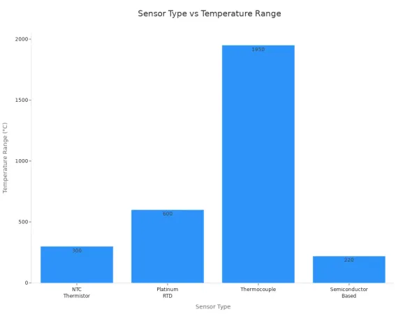
You see that the 10k sensor chart covers a wide range of temperature values, making it useful for many electronic projects. The temperature-to-resistance chart helps you get the most out of your thermistor by giving you the right temperature values for each resistance reading.
You should always check the temperature vs. resistance chart when you set up temperature monitoring in your circuits. This step ensures that your temperature values are correct and your monitoring system is reliable. You can trust the 10k sensor chart to help you achieve accurate temperature measurement in your electronic components and integrated circuits.
Hardware Setup

Required Components
To set up a 10k ohm NTC thermistor for temperature sensing, you need a few essential electronic components. These parts help you build a reliable sensor circuit for accurate temperature control and monitoring.
- 10k ohm NTC thermistor
- Arduino UNO or Genuino UNO microcontroller
- 10k ohm resistor
- 16x2 LCD display for real-time readings
- Connecting wires
You can find high-quality 10k ohm NTC thermistors from trusted manufacturers like Murata Manufacturing Co., Ltd. Their website offers detailed product information and design tools. Many distributors also carry their sensor products, making it easy to source all the hardware you need for your project.
Circuit Connections
You connect the 10k ohm NTC thermistor to your microcontroller using a resistor divider circuit. This simple setup allows you to measure the resistance of the sensor and convert it into a temperature value. The resistor divider is a common topology for thermistor sensing in electronic circuits. For best results, match the reference voltage of the divider to the ADC reference on your microcontroller. This ratiometric measurement improves accuracy and control.
Tip: Use a high-resolution ADC (12-bit or higher) to ensure the measurement accuracy is limited by the sensor, not the converter.
For reliable sensing and control, follow these best practices:
- Use a four-wire (Kelvin) measurement technique to eliminate lead resistance errors.
- Ensure good thermal contact between the sensor and the object you want to measure. Apply thermally conductive paste or epoxy for better heat transfer.
- Shield the sensor from drafts and electromagnetic interference (EMI) to prevent noise in your readings.
- Avoid running sensor cables near AC wiring to reduce interference.
- Check the minimum wire size and maximum cable length recommended by your controller manufacturer.
- Use gel-filled connectors for outdoor joints to protect your sensor wiring.
Proper sensor placement is key. Mount the sensor where it can accurately reflect the temperature you want to control. Avoid strong electromagnetic fields, as they can affect your sensing circuit.
Programming and Calibration
Integrating the 10k Sensor Chart
You need to connect your sensor readings to real temperature values. The 10k sensor chart helps you do this. When you build your electronic circuit, you use a microcontroller to read the voltage from the sensor. The microcontroller converts this voltage into a resistance value. You then use the 10k sensor chart or a mathematical formula to turn that resistance into a temperature reading.
To get the most accurate temperature reading, you must define the right variables in your code. Here is a simple example using Arduino:
// Define variables for the sensor and calculation
const int sensorPin = A0; // Analog pin for the sensor
const float seriesResistor = 10000.0; // 10k ohm resistor
const float nominalResistance = 10000.0; // 10k ohm at 25°C
const float nominalTemperature = 25.0; // 25°C in Celsius
const float betaCoefficient = 3950.0; // Beta value from datasheet

void setup() {
  Serial.begin(9600);
}

void loop() {
  int adcValue = analogRead(sensorPin);
  float voltage = adcValue * (5.0 / 1023.0);
  float resistance = (5.0 - voltage) * seriesResistor / voltage;
  float steinhart;
  steinhart = resistance / nominalResistance;
  steinhart = log(steinhart);
  steinhart /= betaCoefficient;
  steinhart += 1.0 / (nominalTemperature + 273.15);
  steinhart = 1.0 / steinhart;
  steinhart -= 273.15;
  Serial.print("Temperature: ");
  Serial.print(steinhart);
  Serial.println(" °C");
  delay(1000);
}
You can use the Steinhart-Hart equation or a lookup table from the 10k sensor chart. Both methods help you get a reliable temperature reading from your sensor. If you want to improve your results, you can use software algorithms to correct for non-linearity. These algorithms include:
- Non-linear compensation adjusts the sensor output for more accurate temperature readings.
- Cross-sensitivity compensation reduces errors from other environmental factors.
- Long-term drift compensation keeps your sensor accurate over time.
- Polynomial regression can linearize the relationship between resistance and temperature.
- Progressive polynomial algorithms can further reduce non-linearity and sensor degradation, often achieving less than 1% error.
Tip: Run these algorithms during the initial calibration. This saves time and ensures your sensor gives precise temperature readings in your electronic circuits.
Calibration Steps
You must calibrate your sensor to get the best temperature reading. Calibration matches your sensor output to known temperature values. This process improves the accuracy of your electronic system. Follow these steps to calibrate your 10k ohm NTC thermistor:
| Calibration Step | Description |
|---|---|
| Reference Points | Use reference points that cover the full temperature range you need. For low temperatures, use Galinstan. For high temperatures, use a heat source. |
| Logger Immersion | Submerge your sensor and logger in heated water for 4-12 hours. This lets them reach the same temperature. Move them to room temperature for final readings. |
| Averaging Readings | Take several readings from both your reference sensor and your NTC sensor. Average these readings to reduce lag errors. Use the same set for both sensors. |
| Final Validation | Place all calibrated sensors in a circulating water bath. Check that all readings stay within a 0.1°C band. This confirms your calibration is accurate. |
You should always use reference points that match the temperature range of your application. When you immerse your sensor, you let it reach thermal equilibrium. This step ensures your temperature reading is stable. Averaging readings helps you avoid errors from sudden changes. Final validation checks that your calibration holds across all sensors.
Note: Proper calibration ensures your sensor gives reliable temperature readings in electronic components and integrated circuits.
You can also use software to help with calibration. Many microcontrollers let you store calibration data in memory. You can update this data if you notice drift in your temperature readings over time.
When you finish calibration, your sensor will give you accurate temperature readings. This process is key for any project that needs precise temperature control, such as HVAC systems, industrial controls, or consumer electronics.
Troubleshooting and Best Practices
Common Issues
You may face several common problems when working with 10k ohm NTC thermistors in electronic components and integrated circuits. These issues can affect your temperature readings and the reliability of your system.
- Incorrect measurement setup often leads to errors. Always use a high-quality digital multimeter and check that it is calibrated.
- Inadequate temperature control can cause unstable readings. Use a stable temperature bath or a controlled environment chamber for testing.
- Self-heating effects may occur if you use too much current. Apply the lowest possible excitation current as recommended by the manufacturer.
- Lead resistance can impact your results. Use a four-wire (Kelvin) measurement technique to reduce this effect.
- Damaged or defective thermistors sometimes go unnoticed. Inspect each sensor visually and test its basic function before installation.
- Incorrect application of datasheet values can cause confusion. Review the datasheet for correct parameters and tolerances.
- Environmental factors such as humidity and dust can lead to drift or failure. Store and test thermistors in a clean, dry place.
Note: Excessive solder or mechanical stress can crack the thermistor. Use the right amount of solder and design your circuit board to minimize stress.
If you notice melting of the ceramic body, check your circuit for overcurrent. Always keep the current within the specified range.
Reliable Performance Tips
You can improve the performance and accuracy of your temperature measurements by following these best practices:
- Check all connections for security before testing.
- Set your multimeter correctly to measure resistance.
- Retest the thermistor after making any adjustments.
- Try different voltage supplies, such as 3.3V and 5V. You may find that 3.3V works better at lower temperature ranges, while 5V may be more accurate at higher temperatures.
- If the thermistor does not respond to heat, check for damage or poor connections.
- Place the sensor away from sources of electrical noise and strong drafts.
- Address environmental factors. High humidity or temperature outside the rated range can cause corrosion or mold, leading to unstable resistance and erratic readings.
Tip: Store your sensors in a dry, clean environment to prevent corrosion and ensure long-term stability.
By following these steps, you can achieve reliable temperature readings and extend the life of your 10k ohm NTC thermistor in your electronic circuits.
Mastering the 10k sensor chart helps you achieve accurate temperature measurement in electronic circuits.
An NTC thermistor is highly sensitive and accurate, cost-effective, and has a fast response time, making it ideal for precise temperature measurements. However, it has a non-linear resistance-temperature relationship and can suffer from self-heating, which may affect accuracy.
To keep your sensor reliable, follow these tips:
- Calibrate your sensor for your specific application.
- Use shielded cables to reduce noise.
- Inspect probes and cables for damage.
- Recalibrate regularly and stay within the recommended temperature range.
By following these steps, you ensure consistent performance in your integrated circuits.
FAQ
What does a 10k NTC thermistor do in a circuit?
A 10k NTC thermistor measures temperature by changing its resistance. You use it in electronic circuits to monitor or control temperature. Many integrated circuits rely on this sensor for accurate readings.
How do you connect a 10k thermistor to a microcontroller?
You connect the thermistor in a voltage divider circuit. One end goes to voltage, the other to ground, and the middle connects to an analog input. This setup lets your microcontroller read temperature changes.
Why does the resistance of a 10k NTC thermistor decrease with heat?
NTC stands for Negative Temperature Coefficient. When temperature rises, the thermistor’s resistance drops. This property helps you detect temperature changes in electronic components and integrated circuits.
How often should you calibrate your 10k thermistor?
You should calibrate your thermistor before first use and then check it every few months. Regular calibration keeps your temperature readings accurate in your electronic projects.
Can you use a 10k NTC thermistor in high-temperature environments?
Most 10k NTC thermistors work up to 125°C. Check the datasheet for your sensor’s maximum rating. Using it above this temperature can damage the sensor and affect your circuit’s reliability.


