

Step-by-Step Guide to Identifying USB Male Pinout
You might wonder how to quickly spot the right usb male pinout when working with electronic components or integrated circuit
You might wonder how to quickly spot the right usb male pinout when working with electronic components or integrated circuits. Understanding the universal serial bus and its usb pinout helps you prevent damage and ensures safe data or power transfer. When you handle a usb device, knowing the correct usb male pinout keeps your circuits working safely and efficiently.
Key Takeaways
- Understanding USB pinouts is crucial for safe and efficient connections in electronic projects. It helps prevent damage to components and ensures proper data transfer.
- Always inspect the USB connector type and orientation before making connections. This step helps avoid mistakes that can lead to short circuits or device failure.
- Use a USB pinout diagram to match physical pins to their functions. This practice ensures accurate connections and protects your electronic components.
- Familiarize yourself with standard color codes for USB cables: red for power, black for ground, and white/green for data. This knowledge simplifies pin identification.
- Test USB connectors with a multimeter to verify pin functions and continuity. This precaution helps ensure safe operation and prevents costly errors.
USB Pinout Basics
What Is a USB Pinout?
A usb pinout shows you how each pin inside a usb connector works. When you look at a universal serial bus, you see a small plug with metal contacts. Each contact, or pin, has a special job. You use a pinout to match these pins to their functions. This helps you connect electronic components and integrated circuits safely.
Here is a table that explains the standard pinout for most usb connectors:
| Pin | Function Description |
|---|---|
| VBUS | Supplies power to the connected device through the USB port. |
| D+ | Transmits digital signals for data communication between devices. |
| D- | Receives digital signals for data communication between devices. |
| ID | Identifies the role of the device (host or peripheral) in the USB connection. |
| GND | Provides a common reference point for the electrical circuit, ensuring stability. |
You can see that each pin supports either power, data transfer, or device identification. When you work with a usb pinout, you make sure your circuits get the right signals and power.
Why USB Pinouts Matter
You need to understand usb pinouts to keep your projects safe and working. If you connect the wrong pins, you risk damaging your electronic components or losing data. Here are some reasons why knowing the pinout is important:
- You can identify correct connections, which prevents short circuits and overloads.
- You choose the right cables and connectors, so you avoid mistakes.
- You use powered hubs to reduce risks from high-voltage differences.
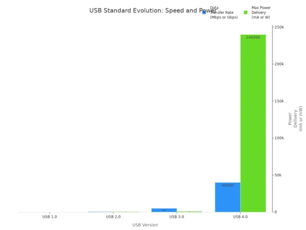
USB pinout standards have changed over time to support new devices and faster data transfer. The table below shows how usb versions have improved:
| USB Version | Release Year | Data Transfer Rate | Power Delivery | Key Features |
|---|---|---|---|---|
| USB 1.0 | 1996 | 1.5 Mbps (low), 12 Mbps | N/A | Self-configuring, hot-swappable |
| USB 2.0 | 2000 | 480 Mbps | 5 V, 500 mA | Plug and play, supports multimedia |
| USB 3.0 | 2008 | Up to 5 Gbps | 5 V, 900 mA | Bi-directional transfer, backwards compatible |
| USB 4.0 | 2019 | Up to 40 Gbps | Up to 240 W | Based on Thunderbolt 3, uses Type C connectors |
When you know the usb pinout, you can handle usb power delivery and data transfer with confidence. This skill helps you build reliable circuits and protect your devices.
USB Male Pinout Types
When you work with electronic components and integrated circuits, you often see different types of USB male connectors. Each type has a unique pinout and serves a special purpose in data transfer and power delivery. Knowing how to identify these connectors helps you make safe and reliable connections.
USB Type-A Pinout
You find the USB Type-A connector on most computers and many chargers. This connector is rectangular and easy to recognize. It is the most common usb connector for connecting keyboards, mice, printers, and USB drives. The usb a pinout uses four pins, each with a clear function:
| Pin Number | Function |
|---|---|
| 1 | VCC (+5V) |
| 2 | D- (Data Minus) |
| 3 | D+ (Data Plus) |
| 4 | GND (Ground) |
You use the usb a connector for both data transfer and charging. The simple pinout makes it easy to match each pin to its job. This helps you avoid mistakes when wiring circuits or testing devices.
Tip: Always check the orientation of the usb a connector before plugging it in. This prevents damage to your electronic components.
USB Type-B Pinout
You often see USB Type-B connectors on printers, scanners, and some external hard drives. This connector has a square shape with a slight bevel on one edge. The pinout for Type-B includes five pins:
| Pin | Function |
|---|---|
| 1 | VBUS (power) |
| 2 | D+ (data) |
| 3 | D- (data) |
| 4 | GND (ground) |
| 5 | ID (identification) |
The extra ID pin helps devices know their role in the universal serial bus system. You use this connector when you need stable data transfer and reliable usb power delivery for larger devices.
Micro-USB Pinout
Micro-USB connectors appear on many smartphones, tablets, and small gadgets. You find two main types: Micro-A and Micro-B. Micro-B is the most common for devices. The pin arrangement differs from other usb connectors, especially for USB 3.0, which adds more pins for faster data transfer. This makes Micro-USB a good choice for compact devices that need both charging and data.
- Micro-A connects to the host device.
- Micro-B connects to the peripheral device.
- Micro-B SuperSpeed adds extra pins for USB 3.0 support.
Note: Mini USB connectors look similar but have a different pinout. Always check the connector type before making a connection.
USB-C Pinout
USB-C is the newest and most versatile usb male pinout. You see it on modern laptops, smartphones, and even some automotive electronics. The usb pinout for USB-C uses 24 pins, which allows you to plug it in either way. This reversible design makes it easy to use and reduces wear on your devices.
| Feature | Description |
|---|---|
| Pinout Design | 24-pin, reversible, works in any orientation |
| Data Transfer | Supports speeds up to 40 Gbps |
| Versatility | Handles data, power, and video signals |
USB-C supports advanced protocols and high-speed data transfer. It also delivers more power, making it ideal for charging laptops and powering complex circuits. In 2023, USB Type-C connectors made up 40% of the market, showing their growing importance in consumer electronics.
You can use USB-C for almost any device, from smartphones to integrated circuits in advanced electronics.
Identify USB Male Pinout
Inspect the Connector
Start by looking closely at the usb connector you want to identify. You see different shapes and colors, which help you tell them apart. The usb male pinout depends on the connector type, so pay attention to these details.
- USB Type A connectors have a flat, rectangular shape. You often find them on computers and peripherals.
- USB Type B connectors look square. Printers and scanners use these most often.
- USB Type-C connectors have a symmetrical oblong shape. You can plug them in either way. They support higher speeds and usb power delivery.
- Micro USB-A receptacles are white. Micro USB-B receptacles are black.
You also notice color codes on the ports and plugs:
- USB 1.0 and 2.0 ports are usually white or black.
- USB 3.0 ports are blue.
- USB 3.1 ports are teal blue.
- Sleep-and-charge ports are yellow, orange, or red.
Tip: Always check both the connector shape and the color. This helps you match the usb pinout to the right type and speed.
When you inspect the connector, you make sure you choose the correct usb male pinout for your electronic components or integrated circuits. This step helps you avoid mistakes in data transfer and power connections.
Pin Numbering and Orientation
After you identify the connector type, you need to understand how the pins are numbered and arranged. The pinout changes based on the connector, so you must look at the orientation.
For a usb a connector, hold it with the metal contacts facing up. The pins are numbered from left to right. The usb a pinout uses four pins:
- VCC (+5V)
- D- (Data Minus)
- D+ (Data Plus)
- GND (Ground)
For USB Type-C, you see 24 pins arranged in two rows. The universal serial bus standard makes this connector reversible, so you can plug it in either way. You must use a diagram to match the pins to their functions.
Note: Always check the orientation before connecting. This prevents damage to your electronic components and ensures proper usb power delivery.
Pin numbering helps you match each pin to its job. You use this information to connect integrated circuits safely and support reliable data transfer.
Use a USB Pinout Diagram
A usb pinout diagram gives you a clear map of the pins and their functions. You use the diagram to match the physical pins on your connector to their roles in the circuit. This step is important for accurate identification and safe connections.
Here is a sample table from a usb pinout diagram:
| Pin Name | Function Description |
|---|---|
| D+ | Data positive signal |
| D- | Data negative signal |
| RX1 | Receive data pair 1 |
| TX1 | Transmit data pair 1 |
| CC1 | Configuration channel 1 |
| SBU1 | Sideband use 1 |
| VCONN | Power for active cables |
| B5 | VCONN pin connection |
You use the diagram to check which pin carries power, which pin handles data, and which pin supports special functions. This helps you connect electronic components and integrated circuits without risk.
Tip: Always compare the physical connector to the usb pinout diagram before making any connection. This step helps you avoid short circuits and ensures proper usb power delivery.
You need to remember that the usb pinout depends on both the connector shape and the protocol. The physical connector tells you the type, while the protocol determines the speed and features. By using a diagram, you make sure your usb male pinout matches your project needs.
USB Pin Functions
Power and Data Pins
When you look at any USB connector, you see that each pin has a special job. Some pins carry power, while others handle data. This design helps you connect electronic components and integrated circuits safely.
| Function | Description |
|---|---|
| Power Pins | Two wires for power (VBUS and GND) are used in USB 1.0, 1.1, and 2.0. |
| Data Pins | Two wires for one differential signal of serial data are utilized. |
| Compatibility | USB standards specify dimensions and tolerances to prevent physical incompatibilities. |
| Charging Modes | Charging docks supply power without data connections, allowing devices to charge from standard cables. |
You use the power pins (VBUS and GND) to deliver energy to your device. The data pins (D+ and D-) help with data transfer between your computer and your device. This setup keeps your circuits safe and makes sure your devices work as expected.
Proper grounding is very important. The ground pin acts as a safety net. It prevents voltage build-up, which can damage your device or cause data transfer failures. Always check the pin arrangement before connecting anything.
USB A Pinout Details
The USB A connector is the most common type you will find in computers and many electronic projects. You need to know the exact pinout to avoid mistakes when working with integrated circuits or building your own cables.
| Pin | Name | Cable Color | Description |
|---|---|---|---|
| 1 | VCC | Red | +5 VDC power supply pin |
| 2 | D- | White | Data- pin |
| 3 | D+ | Green | USB data cable Data+ |
| 4 | GND | Black | Ground pin |
The USB A pinout uses four pins. Two pins (VCC and GND) supply power. The other two pins (D+ and D-) handle data. The power pins give your device a steady +5V, while the data pins let your device send and receive information. This simple arrangement makes it easy for you to connect electronic components and integrated circuits without confusion.
Tip: Always match the cable colors to the correct pins when you build or repair a USB cable. This helps you avoid short circuits and keeps your devices safe.
Special Cases (2-Pin, Multi-Pin)
Sometimes, you will see USB connectors with a different number of pins. Some charging cables only use two pins for power. These cables do not support data transfer. You use them when you only need to charge a device, not exchange information.
Multi-pin connectors, like USB Type-C, can have up to 24 pins. This design supports faster data transfer, higher power delivery, and even video signals. In some cases, USB Type-C connectors made for power-only operation remove the data pins. This change allows for higher power ratings and reduces the risk of failure.
- 2-Pin Cables: Only VBUS and GND are present. You use these for charging docks or simple power supplies.
- Multi-Pin Connectors: More pins mean more features. You get faster speeds, better power delivery, and extra functions like video output.
The arrangement of pins in any USB connector is critical. If you connect the wrong pins, you risk damaging your electronic components or causing your integrated circuits to fail. Always use a pinout diagram and double-check your connections.
Note: Proper grounding in every USB pinout is essential. The ground pin keeps your device stable and safe, preventing overheating and data loss.
You can see that understanding the function and arrangement of each pin helps you build reliable circuits and protect your devices. This knowledge is key when you work with the usb male pinout in any electronics project.
USB Pinout Diagram Reference
Reading a USB Pinout Diagram
You often use a usb pinout diagram when you work with electronic components or integrated circuits. These diagrams show you the layout of each pin inside a usb connector. You see how each wire connects to a specific function, such as power or data. When you read a diagram, you match the physical pins to their roles. This helps you avoid mistakes and keeps your circuits safe.
Start by looking for the labels on the diagram. You see names like VBUS, D+, D-, and GND. Each label tells you what the pin does. For example, VBUS supplies power, while D+ and D- handle data signals. GND provides a stable ground for your circuit. You also notice the orientation of the connector. Diagrams usually show the front view or the soldering side. Always check which side you are looking at before you connect anything.
Tip: Use the diagram to double-check your connections before you solder or plug in a usb connector. This step protects your integrated circuits from damage.
Common Diagram Symbols
You see several symbols and notations in a usb pinout diagram. These symbols help you understand the function of each wire and pin. Color coding is one of the most important features. You find the following colors in most diagrams:
- Red wire: Positive power supply (5V DC)
- Black wire: Ground (GND)
- White wire: Positive data (D+)
- Green wire: Negative data (D-)
These colors make it easy for you to identify the correct wires when you build or repair cables for electronic components.
You also see logos and symbols for different universal serial bus versions. These symbols tell you the speed and features of the usb connector. Here is a table that shows common USB version symbols:
| USB Version | Logo | Max Speed | Data Transfer | Audio | Video | Power Delivery |
|---|---|---|---|---|---|---|
| USB 2.0 | Trident symbol only | 480 Mbps | ✓ | X | X | X |
| USB 3.2 Gen 1 | SS + 5 | 5 Gbps | ✓ | ✓ | ✓ | X |
| USB4 | Circle + 40 | 40 Gbps | ✓ | ✓ | ✓ | ✓ |
You use these symbols to choose the right usb connector for your project. When you understand the diagram, you make safe and reliable connections for your electronic components and integrated circuits.
Avoiding Mistakes
Common Errors
You might make mistakes when working with a usb connector and electronic components. These errors can damage your integrated circuits or cause your project to fail. Many people connect the wrong pins or use the wrong cable type. You should always check the pinout before making any connection. Some users forget to match the orientation of the connector, which can lead to short circuits. Others ignore the color codes on wires and connect power to a data pin by accident.
Here are some common errors you should avoid:
- Mixing up the pin numbering on different connector types.
- Using a damaged or worn-out universal serial bus plug.
- Forgetting to check the diagram before soldering wires.
- Ignoring the need for proper grounding.
- Overloading the power pins by connecting too many devices.
Tip: Always inspect your usb connector for bent pins or loose wires before you use it. This simple step can save your electronic components from permanent damage.
Safe Testing Tips
You need to test your usb pinout safely to protect your devices and yourself. When you work with integrated circuits, you should follow safety guidelines. You can use a multimeter to check connections, but always start with the device powered off. Never touch exposed wires while the circuit is live.
Follow these safety tips when testing:
- Encrypt any local storage on your device to keep sensitive data safe.
- Prevent unauthorized usb devices from connecting by setting strict policies.
- Disable auto-run features on your computer to avoid harmful software.
- Wear anti-static wrist straps when handling integrated circuits.
- Use insulated tools to prevent accidental shorts.
- Double-check your pinout diagram before applying power.
Note: Careful testing helps you avoid costly mistakes and keeps your universal serial bus projects running smoothly.
Troubleshooting USB Pinout Issues
Unlabeled or Damaged Connectors
You may find a usb connector with no labels or visible damage. This situation can make it hard to identify the correct usb male pinout. If you work with electronic components or integrated circuits, you need to know which pin does what. Start by inspecting the connector for bent pins, corrosion, or missing pieces. Use a magnifying glass to look closely at the contacts. If you see any broken or loose pins, avoid using the connector. Damaged pins can cause short circuits or harm your universal serial bus devices.
If the connector has no labels, compare its shape and size to standard diagrams. Match the physical layout to a trusted pinout chart. You can also check the cable color codes if they are visible. Red usually means power, black means ground, white and green are for data. Always double-check before connecting to your electronic project.
Tip: If you cannot identify the pins visually, do not guess. Incorrect connections may damage your integrated circuits or cause your usb device to fail.
Verifying with a Multimeter
You can use a multimeter to test the function and continuity of usb male pinout pins. This tool helps you confirm which pin is which, even if the connector is unlabeled or you suspect damage. Follow these steps:
- Disconnect the usb cable from any power source.
- Set your multimeter to continuity or resistance mode.
- Touch the black probe to the ground pin and the red probe to the positive pin.
- Look for a low resistance reading. This shows a continuous path for current flow.
- Optionally, switch your multimeter to voltage mode. Touch the probes to the cable ends to check for voltage.
Testing with a multimeter helps you avoid mistakes when working with electronic components and integrated circuits. You can confirm the correct pinout before you connect anything. This process protects your devices and ensures safe operation.
Note: Always test your universal serial bus connectors before using them in a new project. Careful verification keeps your circuits safe and reliable.
You can identify USB male pinouts by inspecting the connector, checking pin numbers, and using diagrams. Careful inspection helps you avoid mistakes with electronic components and integrated circuits. Follow these best practices for safe and effective work:
- Learn the pin layout and names.
- Read pin descriptions to know each role.
- Use standard color codes for easy identification.
- Double-check pin numbers before connecting.
Explore datasheets and trusted guides for advanced USB pinout projects.
FAQ
How do you identify the correct pinout for usb type a cables?
You inspect the connector and use a pinout diagram. You match each pin to its function. This helps you connect electronic components and integrated circuits safely. Always check the orientation before making any connection.
Why is usb data transmission important for integrated circuits?
You rely on usb data transmission to move information between devices and integrated circuits. Accurate pinout identification ensures signals reach the right components. This prevents errors and keeps your projects working.
Can you use a damaged USB connector with electronic components?
You should avoid using damaged connectors. Bent or broken pins can cause short circuits. This may harm your integrated circuits or stop data transfer. Always inspect connectors before use.
What tools help you test USB pinouts with electronic components?
You use a multimeter to check continuity and voltage. This tool helps you verify each pin’s function. Testing protects your integrated circuits and ensures safe connections.
How do color codes on USB cables help with pinout identification?
You look for standard colors: red for power, black for ground, white and green for data. These colors help you match pins to functions. This makes connecting electronic components and integrated circuits easier.


