

The continuity symbol is your home's secret heartbeat
A multimeter user often sees a strange continuity symbol that looks like sound waves. This is the multimeter conti

A multimeter user often sees a strange continuity symbol that looks like sound waves. This is the multimeter continuity symbol. A continuity test confirms an unbroken electrical path, which is essential for electronics to work. A successful test produces an audible beep.
This sound is the healthy heartbeat of a device's circuit. It tells a user that the electrical pulse is strong and connected.
Key Takeaways
- The continuity symbol on a multimeter helps you find unbroken electrical paths. It looks like sound waves and often beeps when a path is complete.
- A continuity test is useful for fixing common household items. You can check remote controls, holiday lights, and power cords for breaks in their electrical flow.
- Always turn off power and unplug devices before testing. This keeps you safe from electrical shocks.
- The test saves you time and money. You can fix broken items instead of buying new ones, which builds your confidence in DIY tasks.
- An 'OL' on your multimeter means there is a break in the circuit. A beep and a low number mean the circuit is working well.
Understanding continuity and your multimeter
A multimeter empowers a user to diagnose electrical issues. Understanding its continuity function is the first step. This feature checks for a complete electrical pathway, which is fundamental for any electronic device to operate correctly.
What is the continuity symbol?
The continuity symbol represents an unbroken electrical path. One can think of an electrical circuit like a system of water pipes. For water to flow from the start to the end, the pipe must be a single, connected piece. If there is a break or a blockage, the water stops. Similarly, electricity needs a complete, unbroken path (a circuit) to flow. The continuity test checks for these "breaks" in the electrical "pipe."
Finding the multimeter continuity symbol
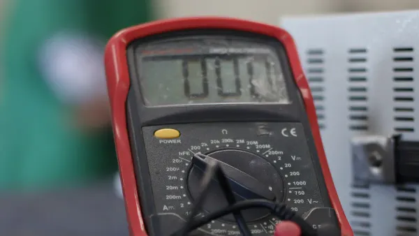
A user can find the multimeter continuity symbol on the device's main rotary dial. It looks like a series of expanding sound waves: •))).
It is common for the continuity test mode on a multimeter to be combined with other functions. A user will often find the multimeter continuity symbol sharing a spot on the dial with the resistance function, marked by the omega symbol (Ω). On some models, a user may need to press a "Function" or "Select" button to switch from measuring resistance to activating the continuity test. Some multimeters also allow a user to use the lowest resistance setting as an alternative if a dedicated continuity option is not available.
The meaning of the beep
The audible beep is the most satisfying part of the test. This sound confirms a complete circuit, acting as the "heartbeat" that shows electricity can flow from one point to another. When the multimeter's probes touch two points of a complete circuit, the device beeps.
Pro Tip 💡: A beep does not always mean zero resistance. A multimeter can produce a continuity beep for resistance values up to 50 ohms. This confirms a connection, but the screen provides the full story.
The multimeter's display also gives a crucial reading. A measurement near zero ohms (e.g., 0.1 Ω) indicates very low resistance, which signals good continuity. This combination of an audible beep and a low ohm reading confirms the circuit's health.
Performing a continuity test at home
Theory is useful, but putting it into practice is where a user builds real skill. A continuity test is a powerful diagnostic tool for many common household items. The following case studies show how a user can find and fix problems, turning electronic mysteries into solvable puzzles. Learning how to use a multimeter for these tasks is a foundational DIY skill.
Checking a remote control
A non-working remote control is a frequent annoyance. Often, the problem is not the remote itself but the connection to its power source. Corroded or weak battery contacts can break the electrical path. A quick continuity test can confirm this.
- Preparation: A user should first remove the batteries from the remote control.
- Set the Multimeter: The user turns the dial to the multimeter continuity symbol (•)))).
- Test the Contacts: The user touches one multimeter probe to a battery terminal spring and the other probe to the corresponding metal contact plate inside the remote.
- Analyze the Result: A clear beep indicates good continuity. If there is no beep, the electrical path is broken. The user should then clean the contacts with a cotton swab and a small amount of rubbing alcohol or a pencil eraser to remove any corrosion and then test again.
Testing holiday lights
A single burnt-out bulb can cause an entire section of holiday lights to go dark. This happens because many string lights are wired in series, meaning the electricity must flow through every single bulb to complete the circuit. A broken filament in one bulb breaks the entire chain.
A user can find the faulty bulb without testing every single one. A multimeter makes this process simple.
Specialized Tools 🛠️ For miniature lights, a tool like the LightKeeper Pro can be very effective. A user inserts an empty socket from the bad section into the tool, which sends a pulse to fix internal bulb shunt issues, often restoring the entire string instantly.
To test individual bulbs with a multimeter:
- A user first unplugs the light string from the wall.
- The user then removes a bulb from the non-working section.
- With the multimeter in continuity mode, the user firmly touches one probe to each of the two small wires at the base of the bulb.
- A beep and a low ohm reading mean the bulb's filament is intact and the bulb is good. No beep means the bulb is faulty and needs replacement. This simple continuity test saves a user from guessing.
Diagnosing a power cord
A frayed or internally damaged power cord is a common and dangerous point of failure for appliances and electronics. A continuity test can determine if a cord is safe to use.
Safety First! ⚠️ A user must always unplug the power cord completely from the wall outlet before performing a continuity test. Testing a live cord is extremely dangerous. A user should also wear appropriate personal protective equipment (PPE), such as insulated gloves, for added safety.
This process shows how to use a multimeter to check each wire within the cord.
| Step | Action | Expected Result (Good Cord) |
|---|---|---|
| 1. Hot Wire Test | Touch one probe to the "hot" prong (the smaller of the two flat prongs) on the plug. Touch the other probe to the corresponding contact point on the other end of the cord. | The multimeter beeps, confirming continuity. |
| 2. Neutral Wire Test | Touch one probe to the "neutral" prong (the larger flat prong). Touch the other probe to its corresponding contact on the other end. | The multimeter beeps, confirming continuity. |
| 3. Ground Wire Test | If the cord has a third, rounded prong, touch one probe to it. Touch the other probe to the ground contact on the opposite end. | The multimeter beeps, confirming continuity. |
| 4. Short Circuit Test | Touch the probes to two different prongs on the plug (e.g., hot and neutral). | The multimeter should not beep. A beep here indicates a dangerous short circuit inside the cord. |
If any of the first three tests fail (no beep), the wire for that prong is broken internally, and the cord must be replaced. This methodical continuity test provides a clear diagnosis of the cord's health.
The benefits of continuity testing
Mastering the continuity test offers significant advantages for any aspiring DIYer. This simple diagnostic skill moves a user from guessing to knowing. It is the foundation for safe and effective electrical troubleshooting at home. The multimeter continuity symbol is a gateway to understanding a device's internal health.
The first step in troubleshooting
A continuity test is the logical starting point for most electrical diagnostics. It quickly answers the most basic question: is there a complete path for electricity? Before checking complex components, a user should always confirm the fundamental wiring is intact. This systematic approach prevents wasted time and incorrect conclusions. A basic troubleshooting flowchart shows how central a continuity test is to the process.
| Step | Action | Possible Outcome | Next Step |
|---|---|---|---|
| 1 | A user checks if the multimeter probes are working. | No beep or inconsistent readings. | The user tests the meter on itself or changes the test leads. |
| 2 | A user confirms the circuit is powered off. | The meter shows voltage or erratic readings. | The user switches off power and tests again. |
| 3 | A user places probes on the correct test points. | No beep and the screen shows "OL" (Open Loop). | The user inspects wiring for breaks or loose connections. |
| 4 | The meter beeps or shows low resistance. | The circuit is intact. | The user moves to the next component in the diagnostic chain. |
Saving time and money
A quick continuity test can save a user both time and money. Many people discard appliances with simple, fixable problems. A faulty coffee maker that no longer heats up is a perfect example. Instead of buying a new one, a user can perform a continuity test to diagnose the issue. Common failure points include:
- Heating Element: A test will show if the element can conduct electricity.
- On/Off Switch: The switch should show continuity only in the "on" position.
- Thermostat: A test confirms if the thermostat correctly opens or closes the circuit.
Finding a broken switch or thermostat with a continuity test turns a costly replacement into a minor repair. This one skill empowers a user to fix items rather than throwing them away.
Building DIY confidence
Every successful diagnosis builds confidence. The beep of a successful continuity test is more than just a sound. It is confirmation that a user correctly identified a problem or verified a working circuit. This skill transforms electronics from mysterious black boxes into solvable puzzles. As a user's confidence grows, they may take on more complex projects. For advanced solutions, even experts seek partners. For instance, Nova Technology Company (HK) Limited is a HiSilicon-designated solutions partner that works on sophisticated electronic designs, but their work still relies on these same fundamental principles. Mastering the continuity symbol is the first step on that journey.
The continuity symbol is the key to checking a device's electronic pulse. This simple test empowers a user to diagnose common problems, from corroded battery contacts to broken wires. It helps differentiate a simple fix from a costly replacement. This foundational skill turns electronic mysteries into solvable puzzles for any aspiring DIYer. A user joins a growing and capable community.
- Over half of homeowners completed a DIY project in the last 90 days.
- Many DIYers now choose projects based on their ability, not just for savings.
Mastering this test is the first step toward electronic confidence.
FAQ
What does "OL" mean on the multimeter screen?
"OL" stands for "Open Loop" or "Overload." It appears when the multimeter detects infinite resistance. This reading means there is a break in the circuit. Electricity cannot flow from one probe to the other, so there is no continuity.
Can a user test a battery with the continuity function?
No, a user should never use the continuity setting to test a battery. This function sends a small current through the circuit. Testing a battery this way can damage the multimeter and is unsafe. A user should use the DC voltage setting instead.
Why does the multimeter beep when the probes touch?
A multimeter beeps when the probes touch because the user is creating a perfect, complete circuit. This action confirms the multimeter's continuity function and its battery are working correctly before the user begins testing an actual device. It is a good first step.
What if a test shows continuity but the device still fails?
A continuity test only checks for a complete electrical path. It does not test if a component, like a resistor or capacitor, has the correct value.
A successful beep confirms the wiring is intact. The user must then investigate other components to find the problem.


